Soyuz clock replica (sort of)

tldr: My version of the soyuz clock featured on CuriousMarc's youtube channel.

This is my attempt at making a replica of the Soyus onboard clock which was featured on CuriousMarc's youtube channel. During the build I realized that the 7 segment displays that I had ordered were too big and my 3d printer wasn't able to recreate the engraved characters on the original clock. So I created a version of the clock that functions the same but looks like it could have been some sort of a prototype or a proof of concept. The back of the clock is both modern and old. I wanted the clock to have multiple ways to be powered. I choose for USB mini, a 6.35 audio jack (because why not?), and screw terminals. Because I do not have a soyuz rocket to connect to my clock I made the relay accessible from the outside but did not add any of the other features that let the rocket interact with the clock.
I want my projects to be as easy as possible to take apart and repair. So I used screws instead of nails or glue as much as possible. To keep the labels in place I used hot glue. It doesn't look very neat but it is not permanent and doing it another way would have added a lot of complexity to the face plate which is already a large print.

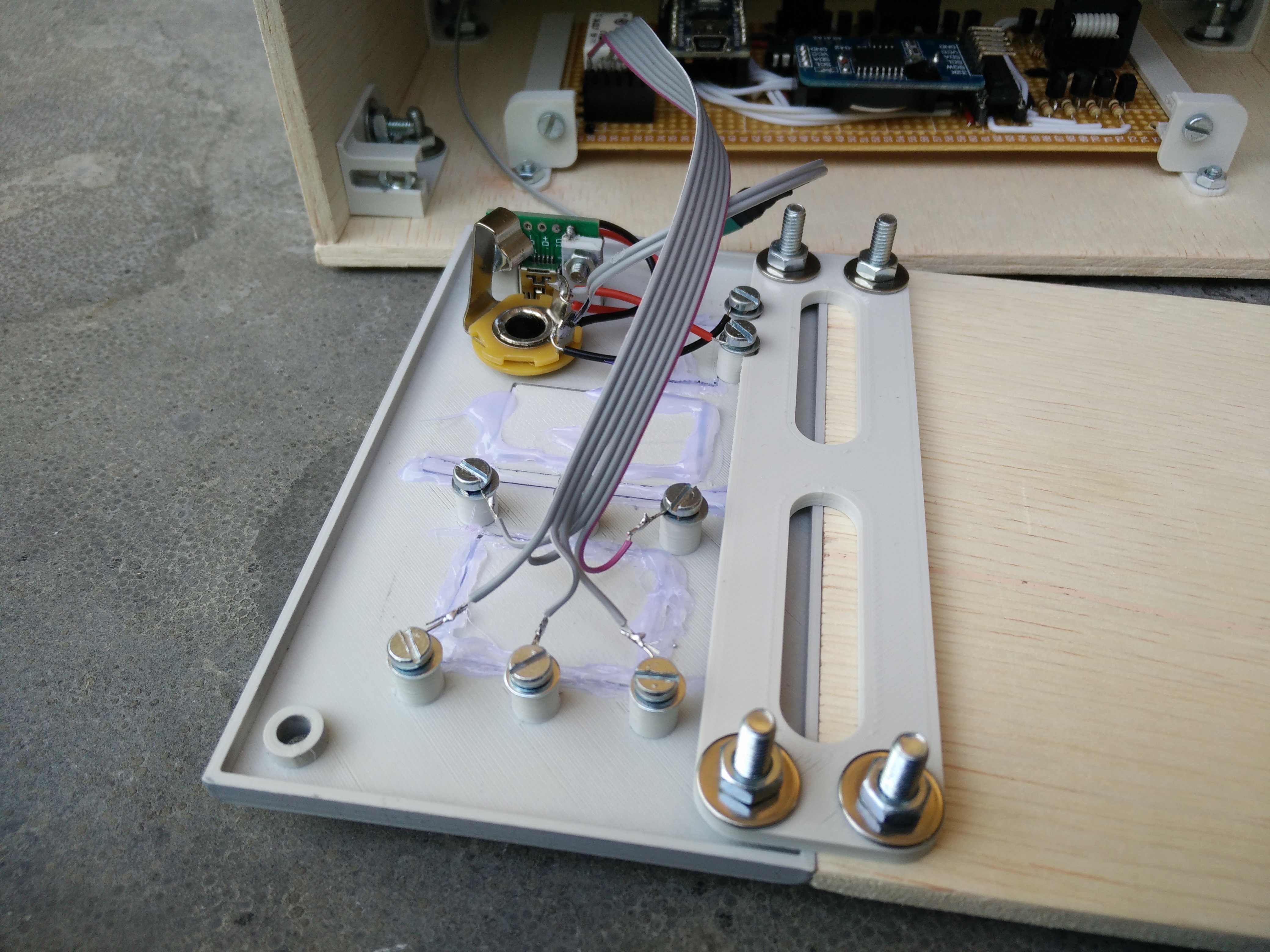
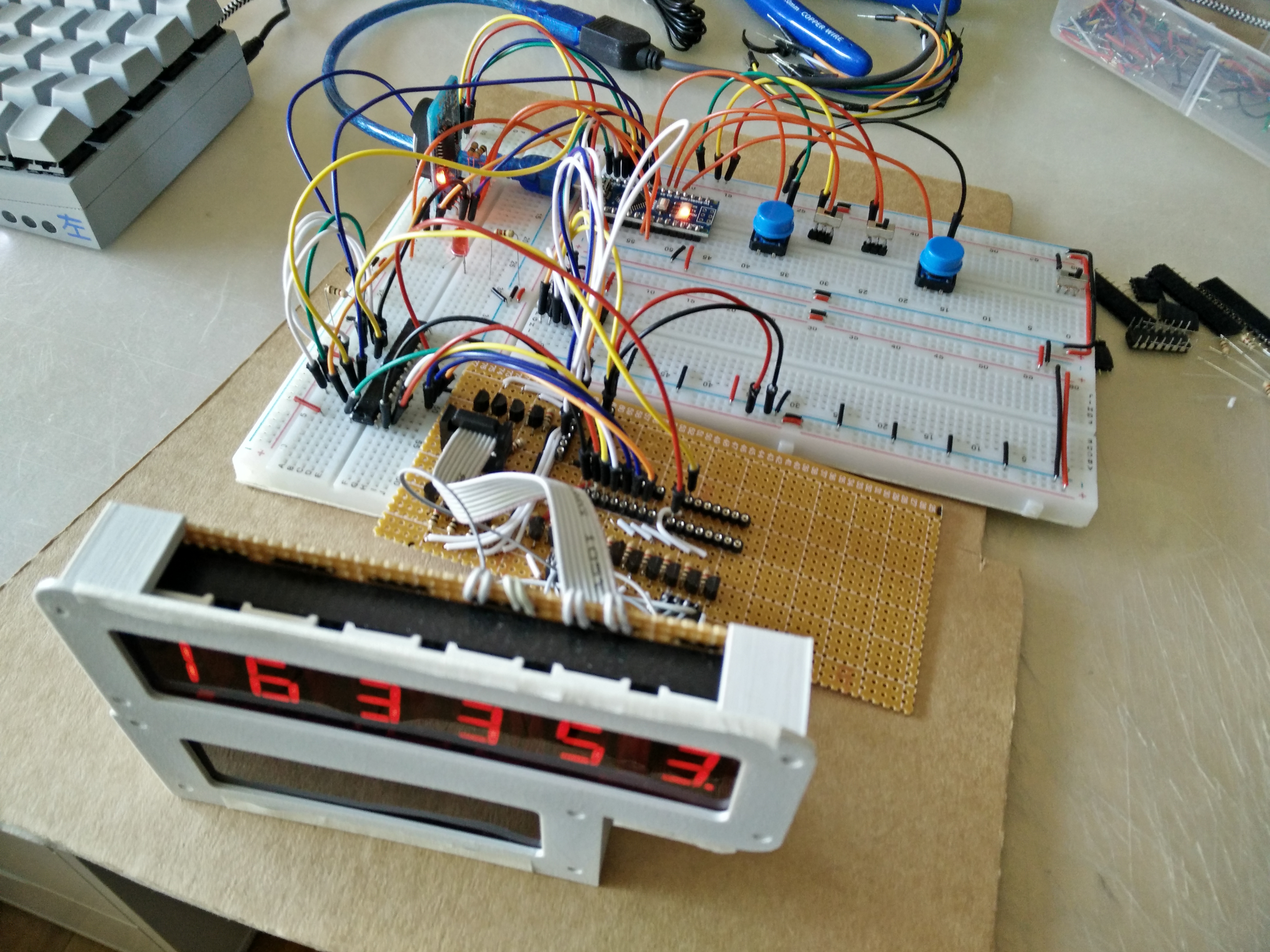
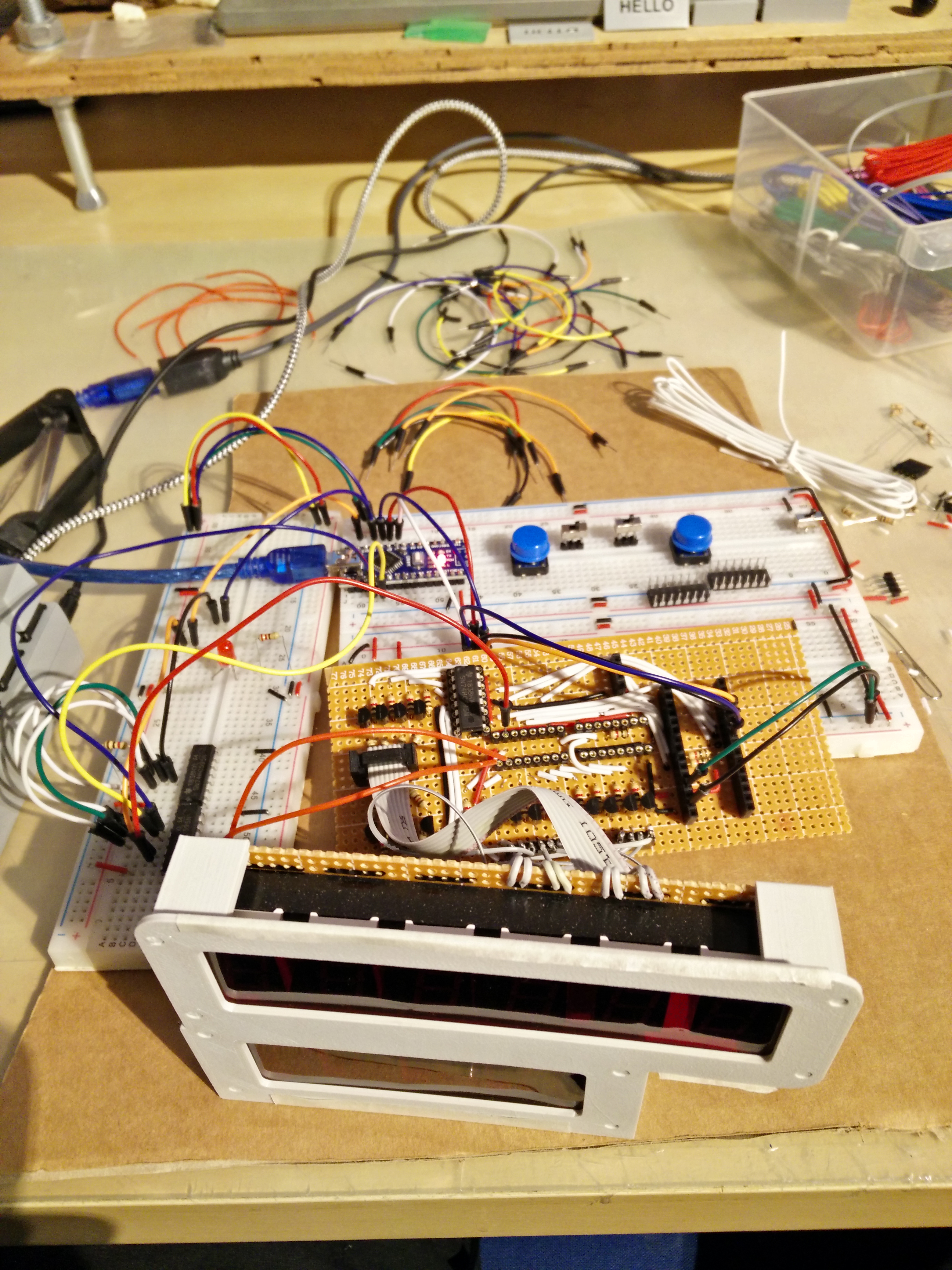
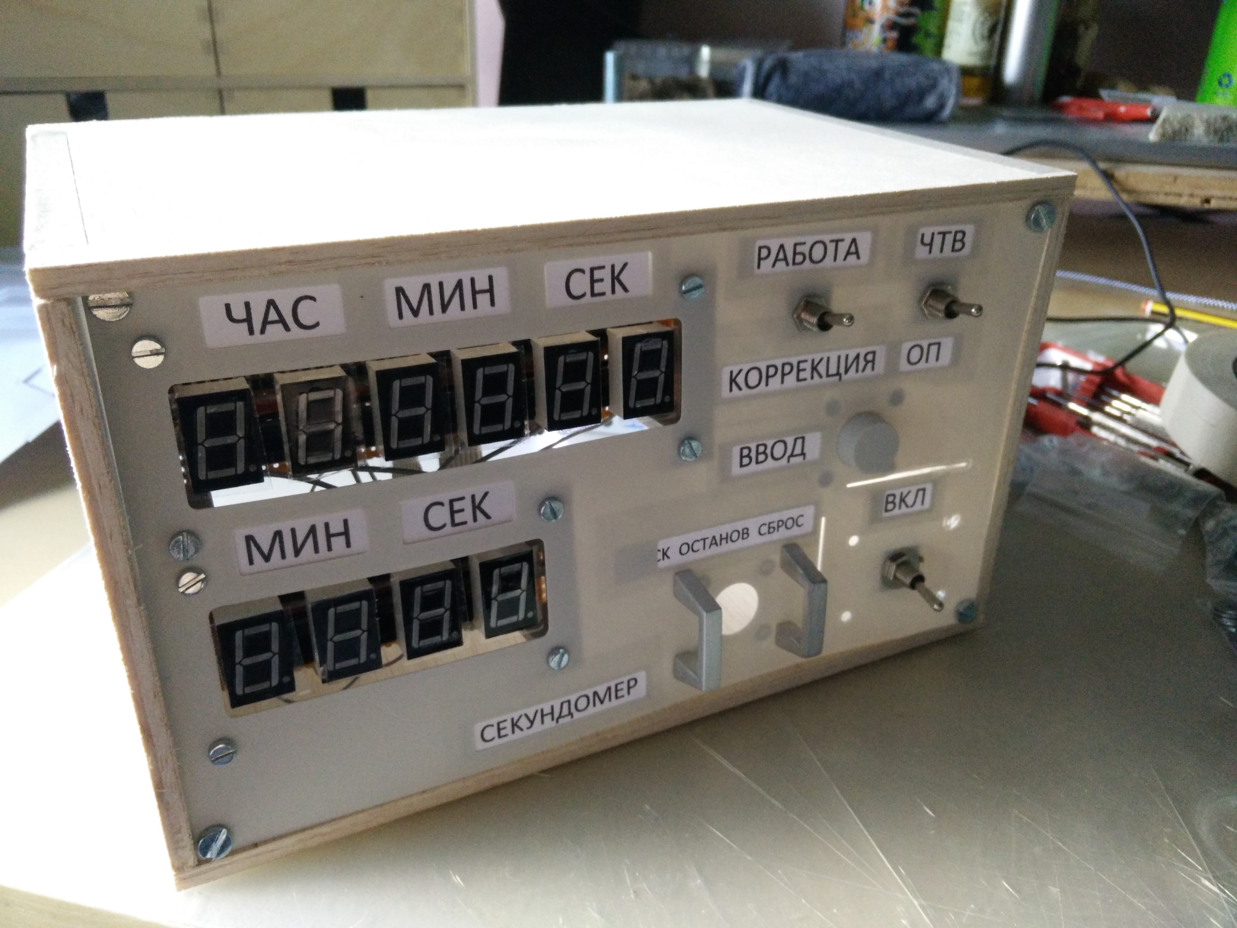
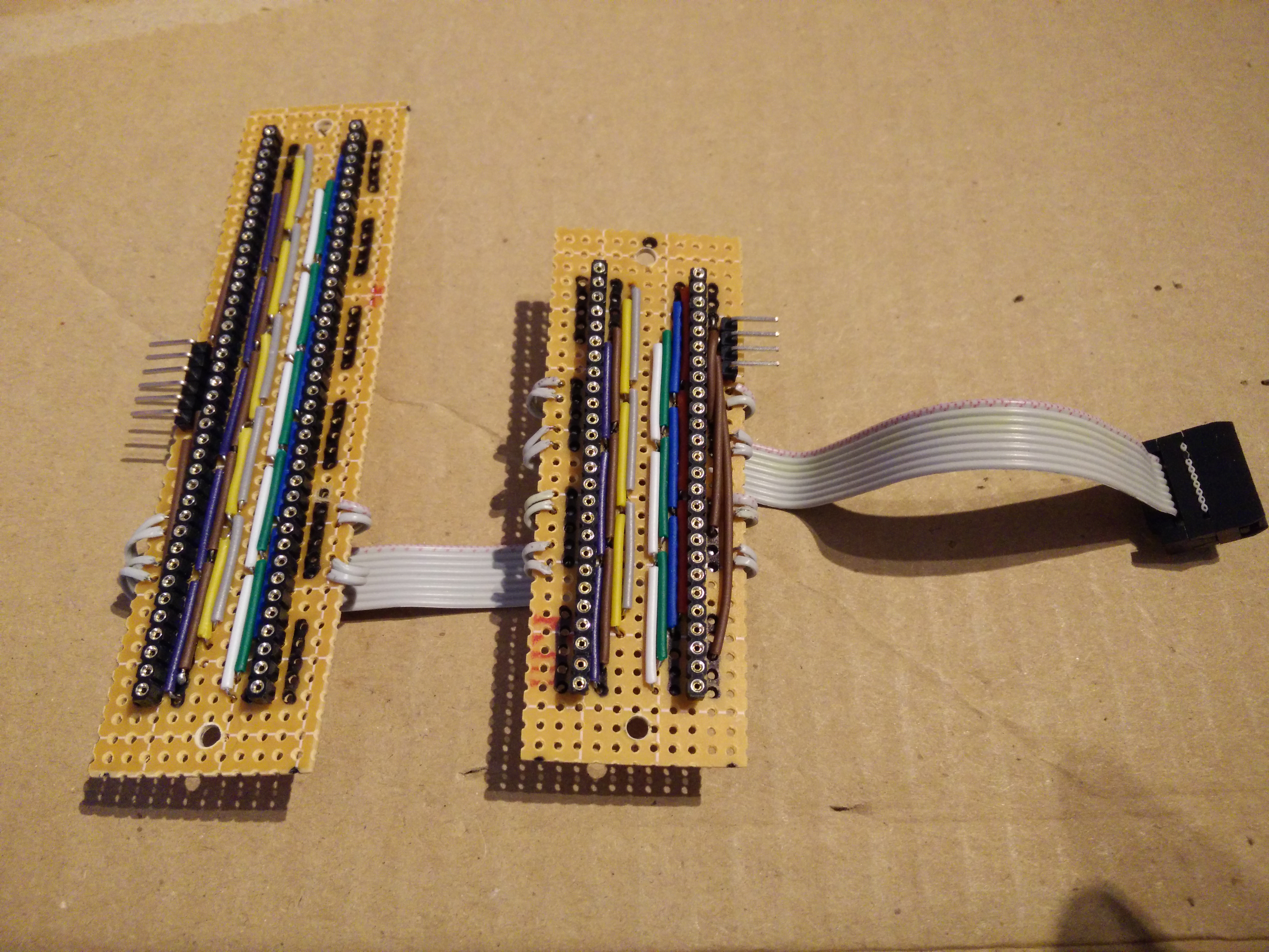
These are some random pictures I took while working on this project. 90% of the electronics were designed and tested on a breadboard. I went through lots of different circuit designs to drive the 7 segment displays. I finally settled on 2 shift registers driving the anodes and 1 shift register driving the cathodes. I could have done the sensible thing and used a driver IC but I wanted to build this out of part's I already had.
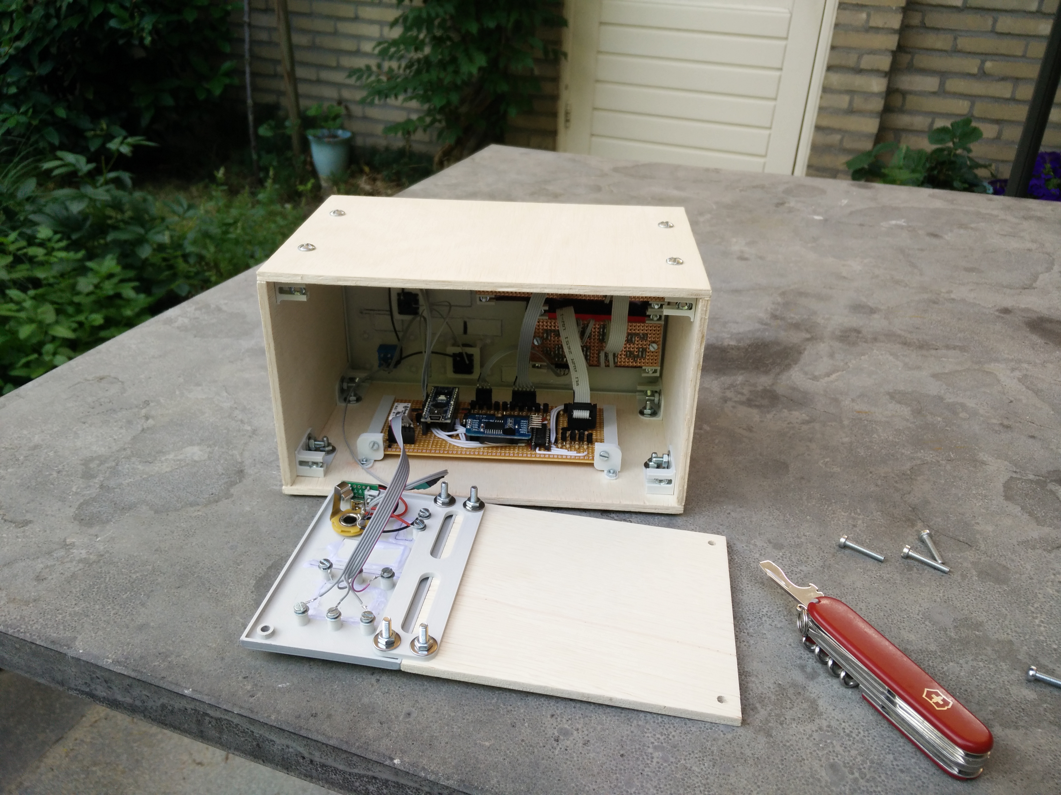
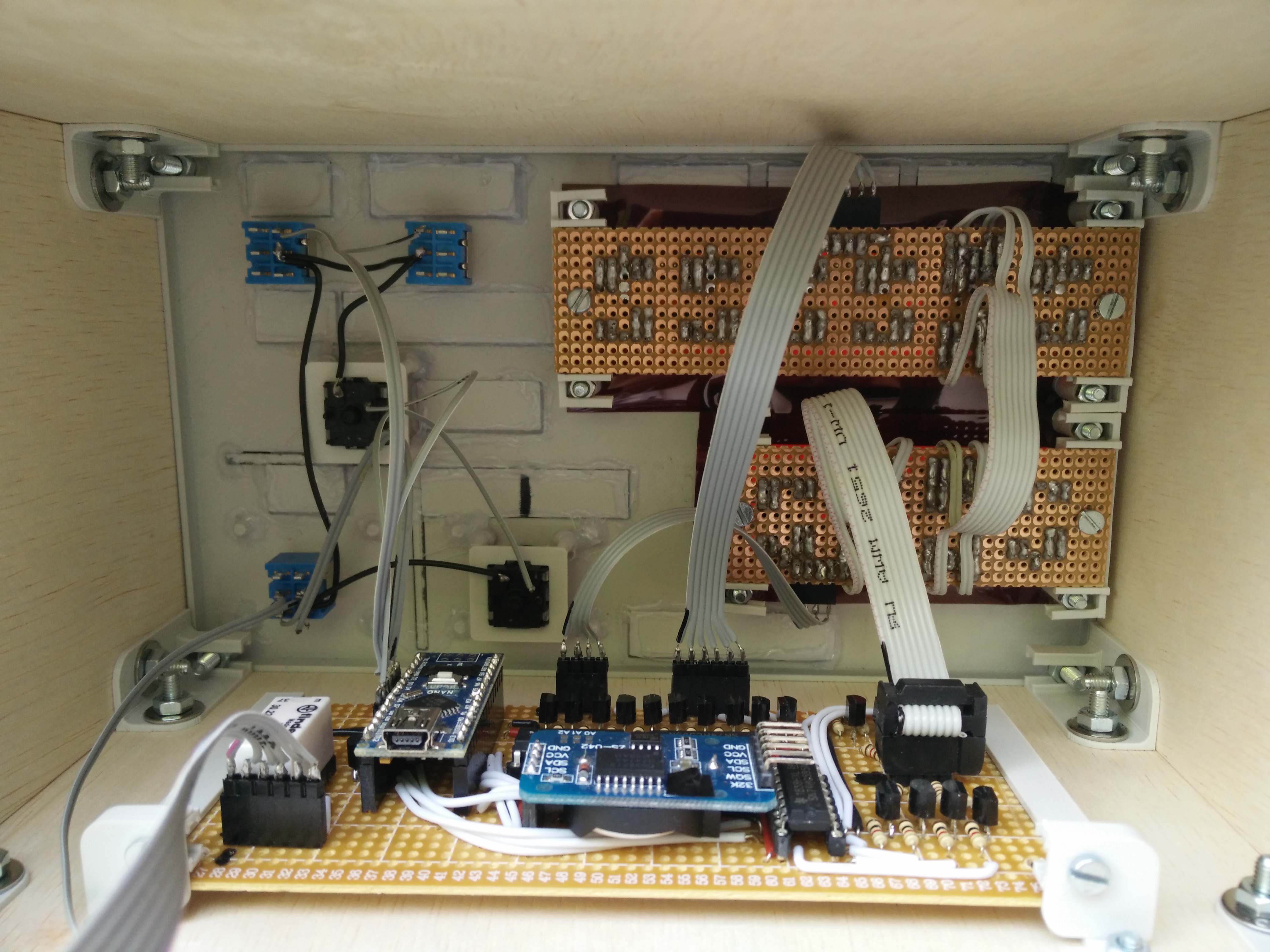
I buffered the shift registers with transistors to prevent them from drawing to much current.
When I was happy with the circuit I started designing a layout on a PCB. During soldering I tested my PCB as much as I could. Before printing the face plate I printed a very thin version of it to see if I got all of my measurements right. After printing I sanded the front and back plate smooth. Certain parts of the print were not very smooth however. I spread a thin layer of superglue over these parts and sanded again. After sanding and painting the parts don't look 3d printed unless you look very closely at them. The last step of this project was redesigning the PCB's which hold the 7 segment displays. As the older one's often randomly lost contact with the taller header connecter that I had used. This was the final mockup I had made before drilling holes in the wooden planks.