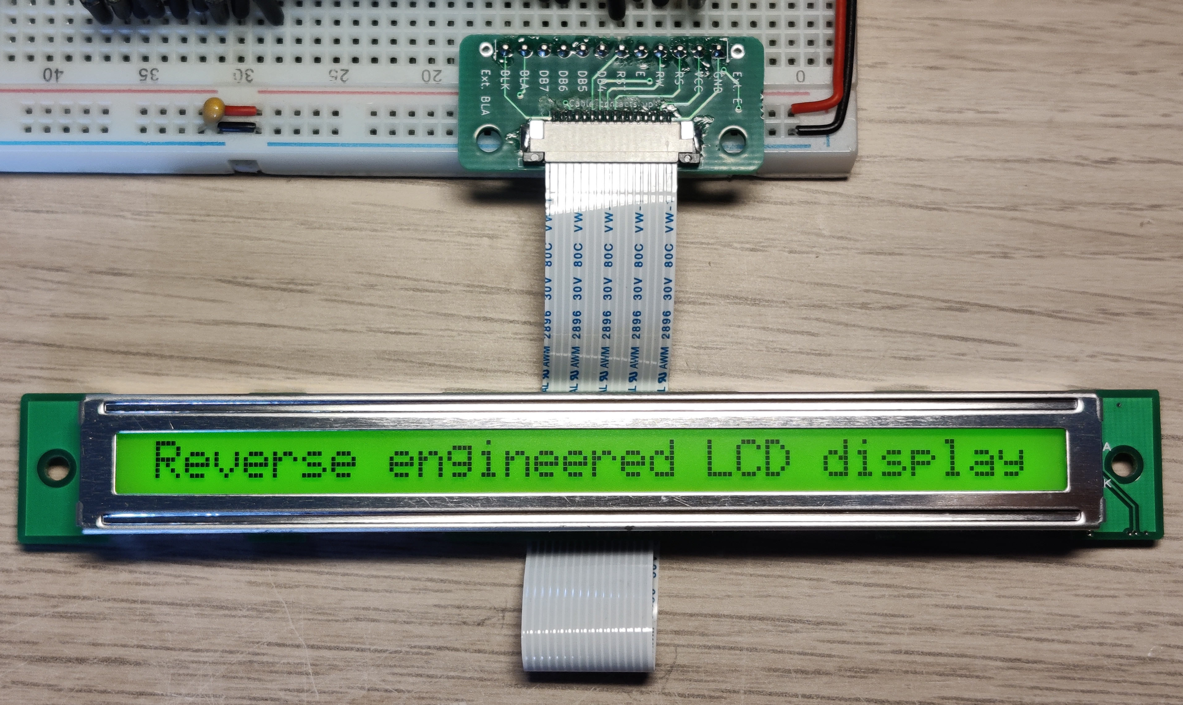
Reverse engineering an LCD display
Intro
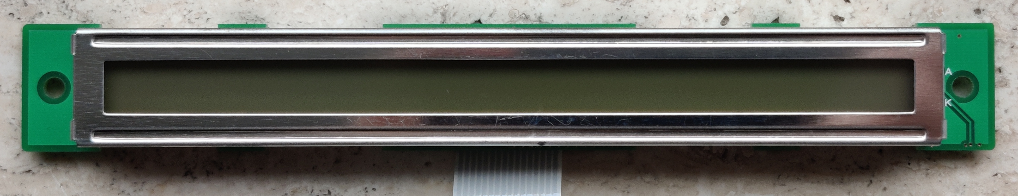
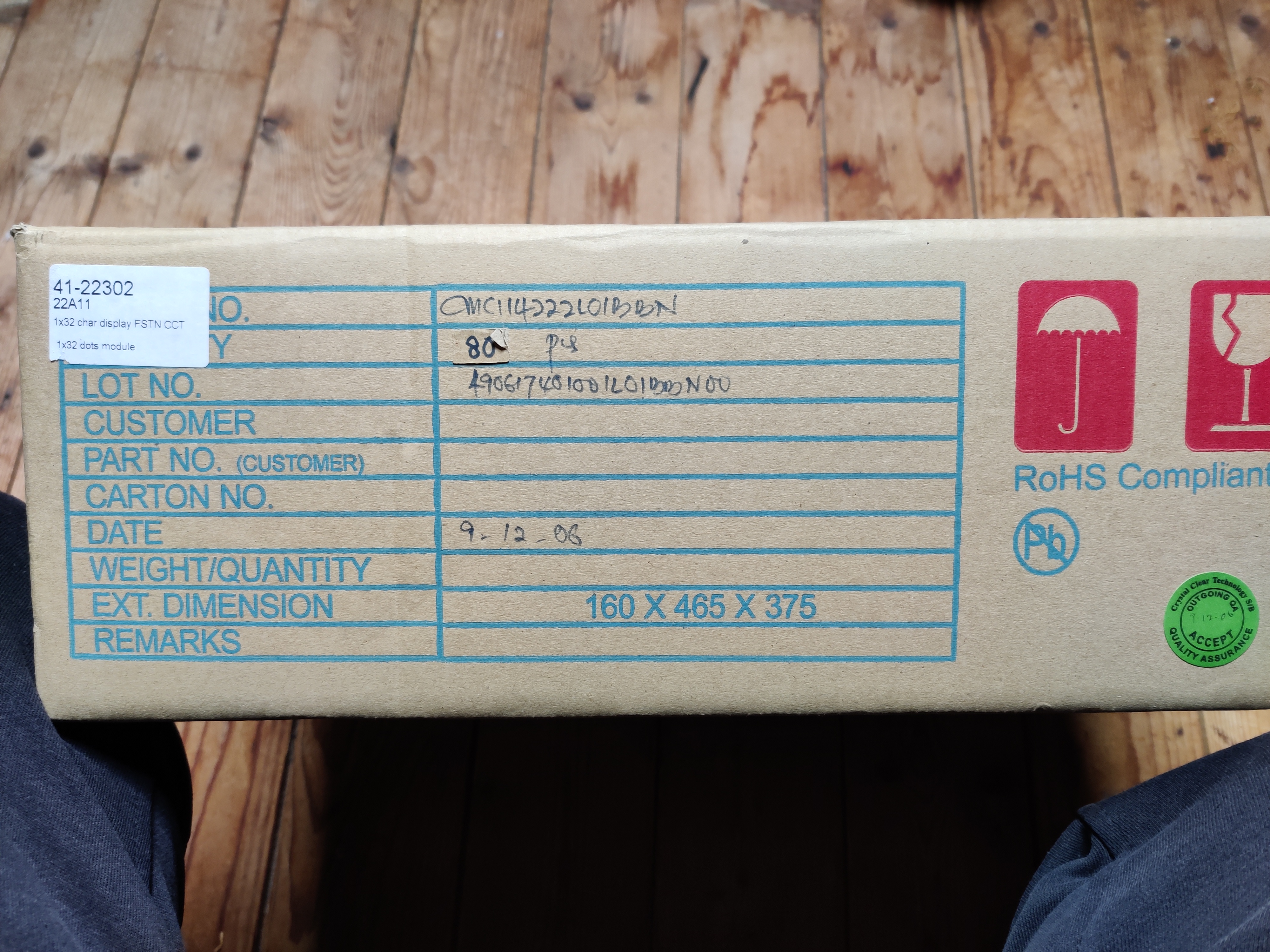
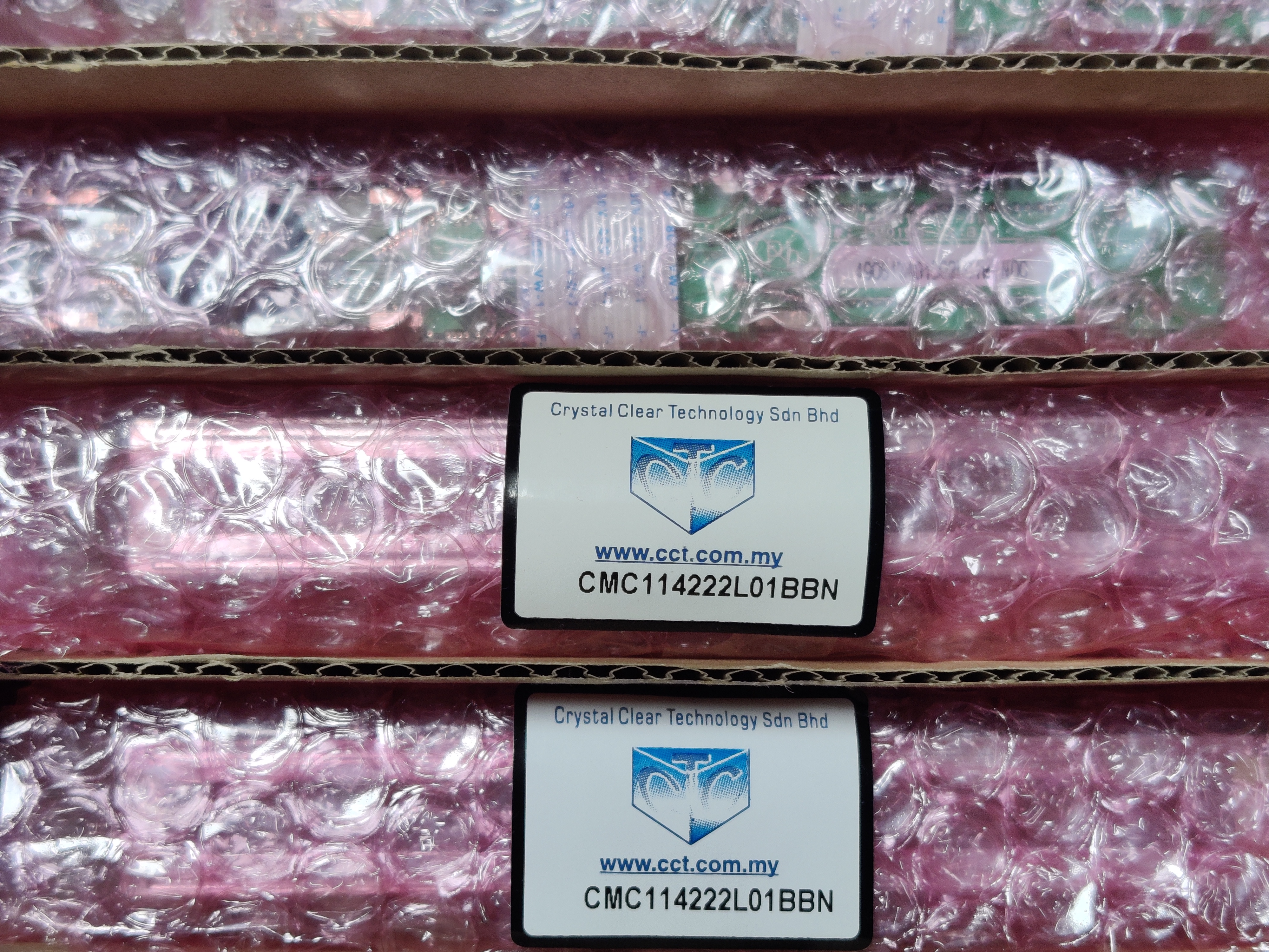
I got a hold of a lot of these 1x32 LCD displays. But I couldn't find a datasheet for them. They didn't seem particularly interesting at first, but throwing out 150+ of them seemed like a huge waste. Thus my reverse engineering journey started!In this article I:
- look for clue's
- trouble shoot
- decap some chips (without acid)
- get a cheap microscope
- fail
- succeed
- design a PCB
Initial steps
The first thing I tried after 'googling it' was taking a look at the website of the manufacturer. They do have a lot of different LCD displays listed but no 1x32 displays. I also tried Thewaybackmachine but that didn't result in anything either.I even emailed them but they didn't want to deal with a hobbyist.
Getting stuck in
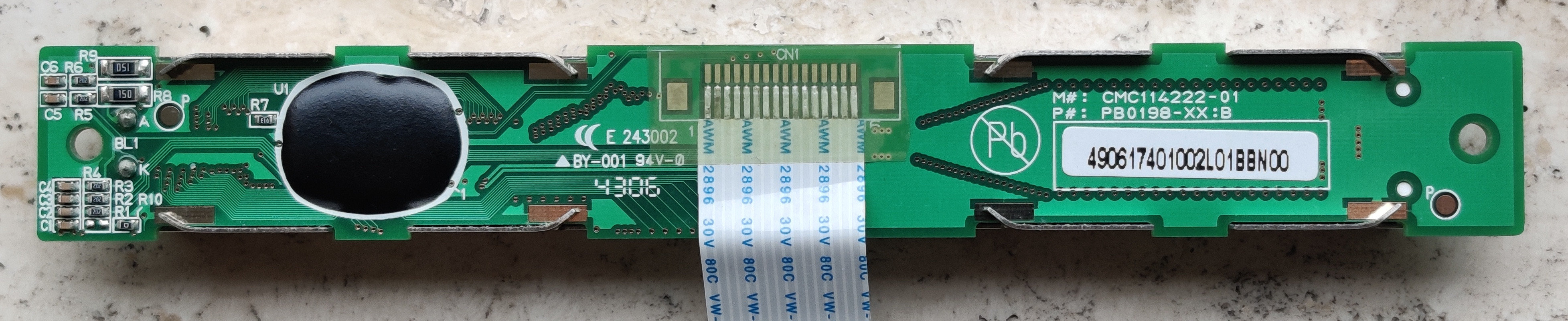
Without a datasheet the 2 main things I needed to know to drive the display are:- The driver chip that is under that black blob
- The Pinout of the display
I realized that the manufacturer does list many 2x16 displays which could be driven by the same driver chip as they have the same amount of characters. Of course I couldn't check this as the driver IC doesn't have any markings because it is a COB.
The datasheet's of the similar displays did include the driver Chip they used. The ST7066, which turns out to be the same chip used in most of the common Arduino-compatible LCD displays. Although many of these probably also use other compatible drivers like the HD44780. Which adds some complexity to the situation.
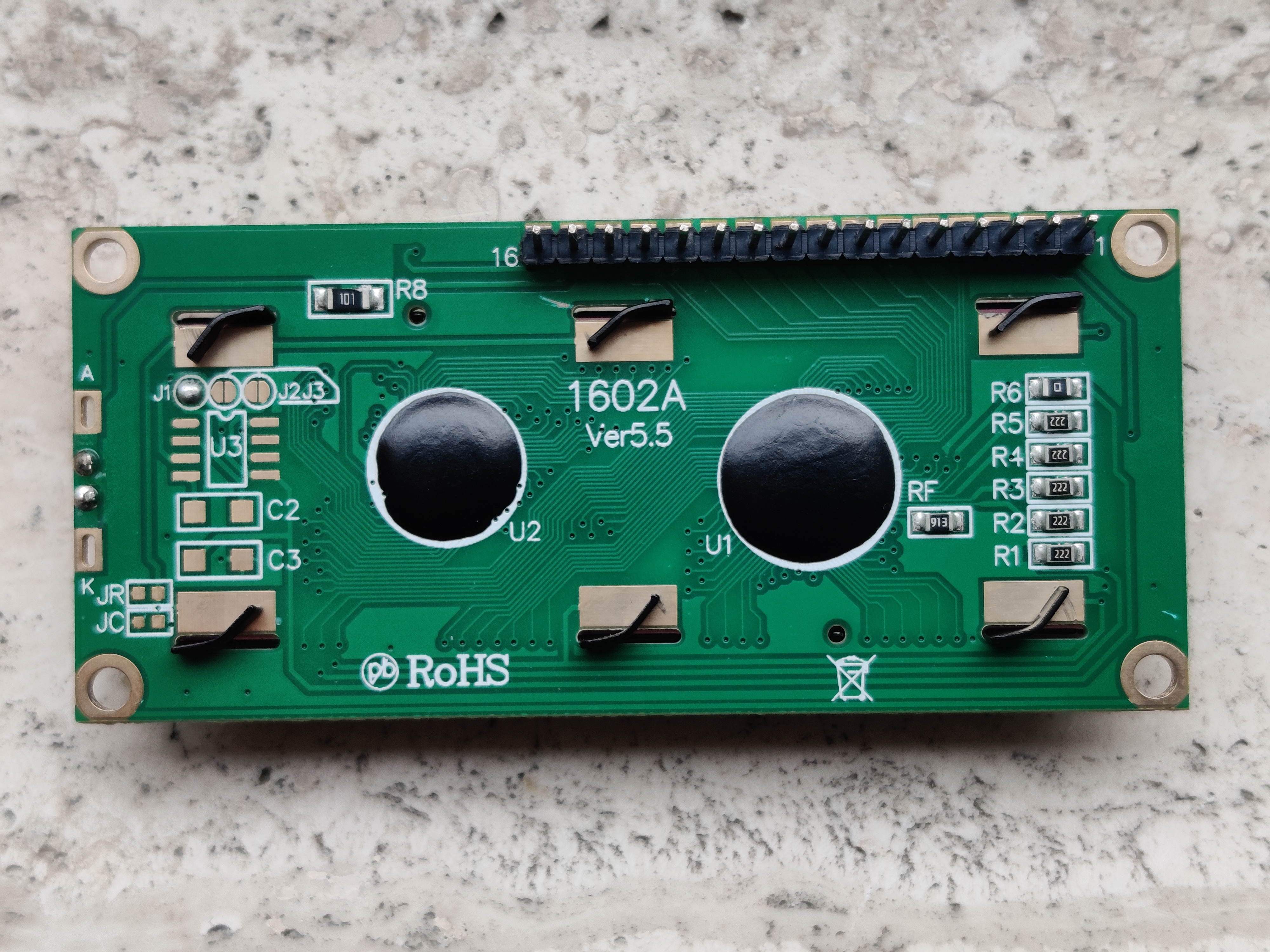
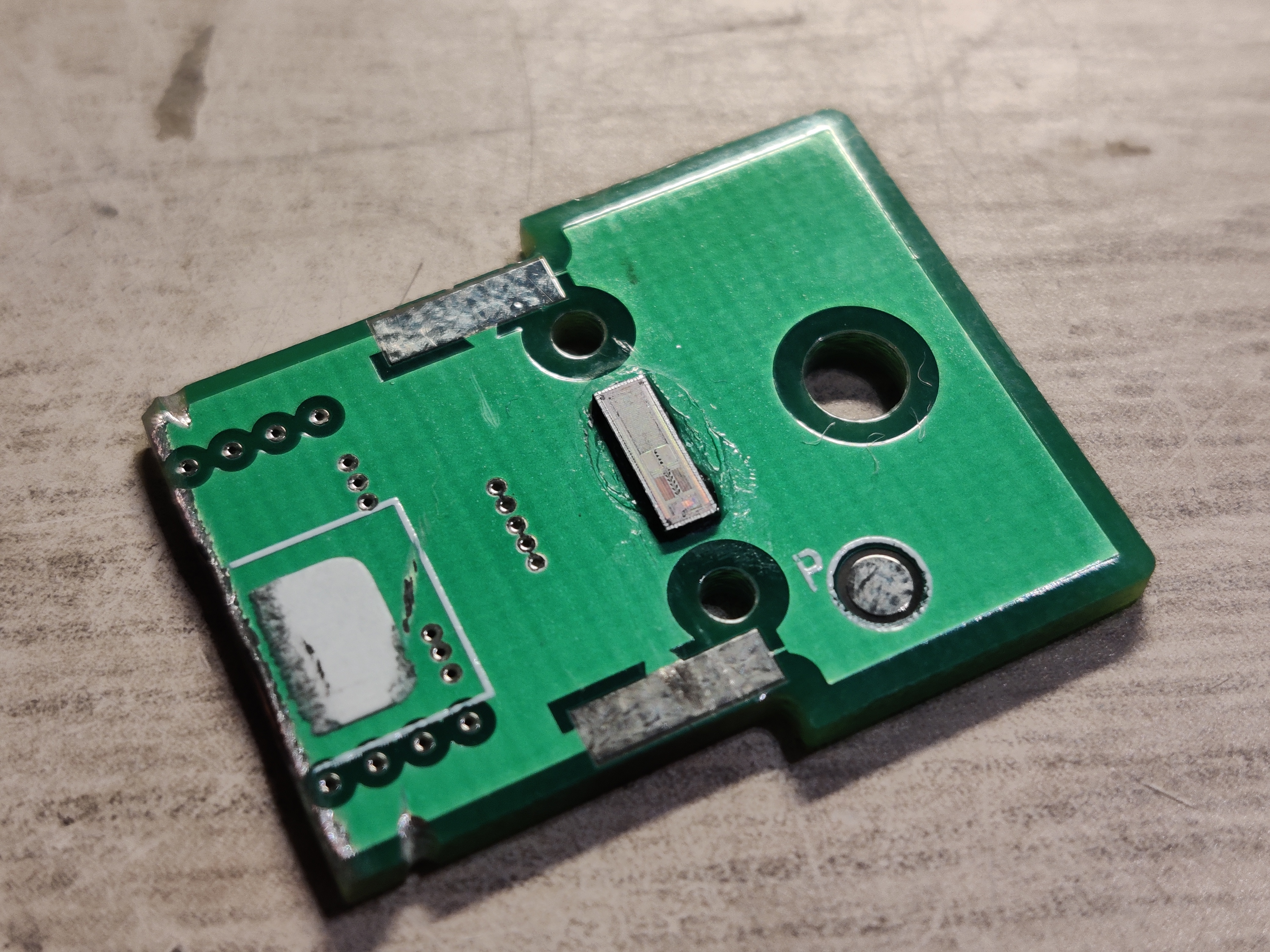
Looking at the ST7066's datasheet I realized that the required external components could also be found on my display's PCB. I was able to confirm with a multimeter that they were connected in the same way as mentioned in the datasheet.
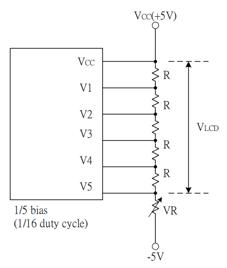
External components (voltage divider) from the ST7066's datasheet
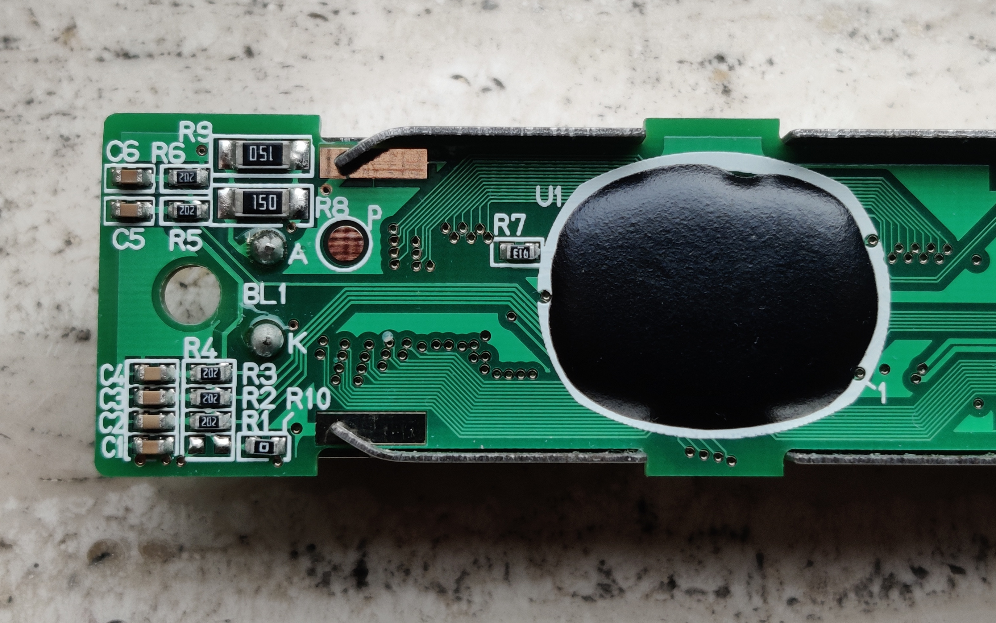
External components on the PCB
The common Arduino-compatible displays almost all have the same pinout. Mine have the same number of pins but after quickly measuring around a bit I could already tell that they don't match as the backlight pins were in a different position. But based on the configuration of the external components I was able to measure that GND and Vcc were in the same position!
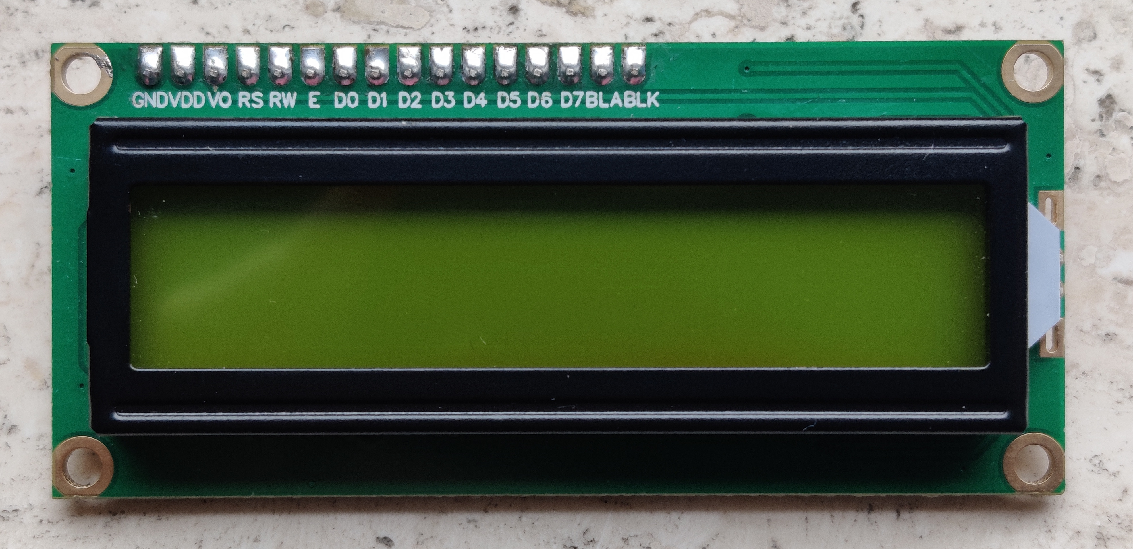
Common 2x16 LCD
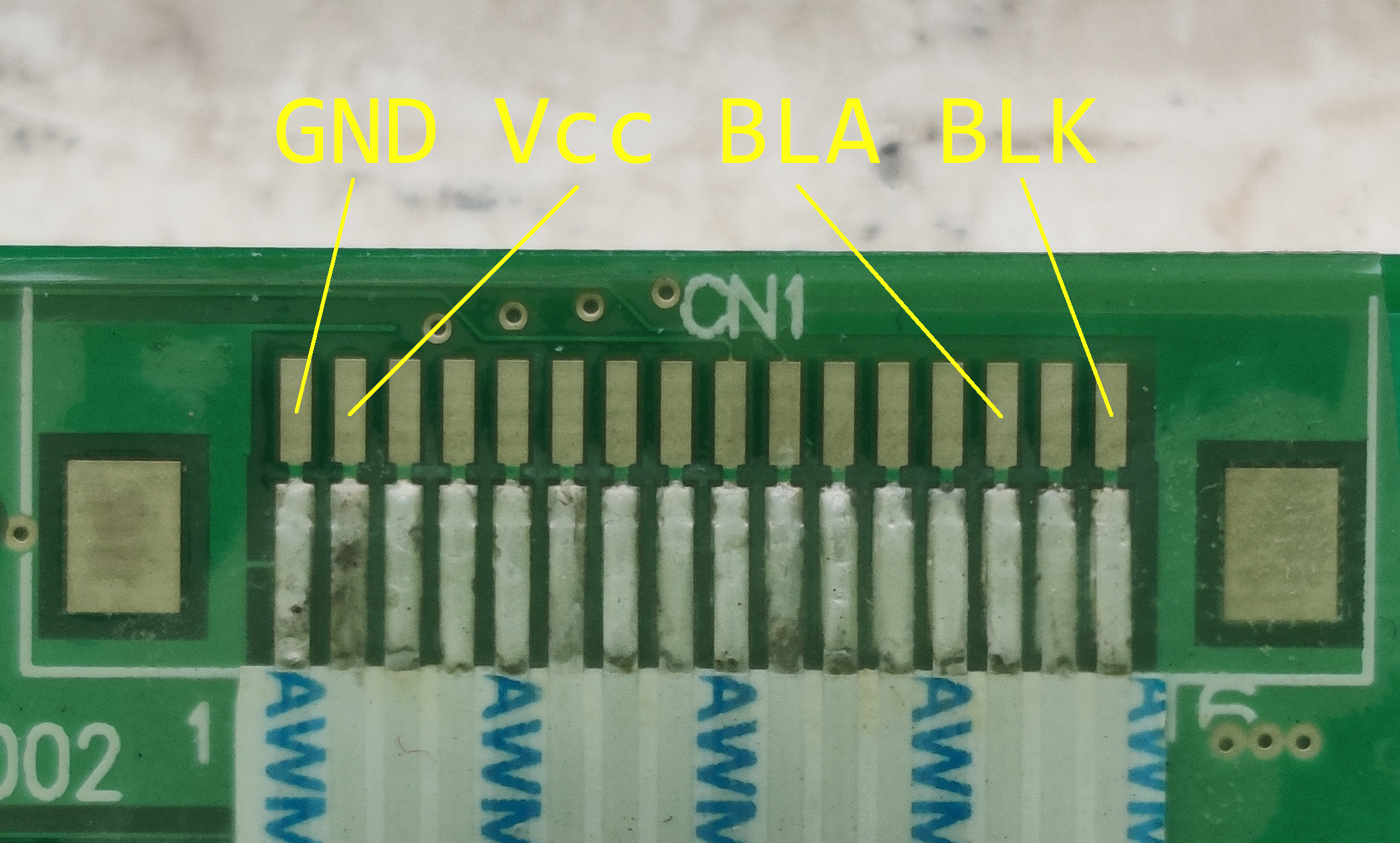
Partial pinout of the mystery display
The driver was indeed alive as I was able to measure LCD driving waveforms and the different voltage levels produced by the external components. This was my first small victory!
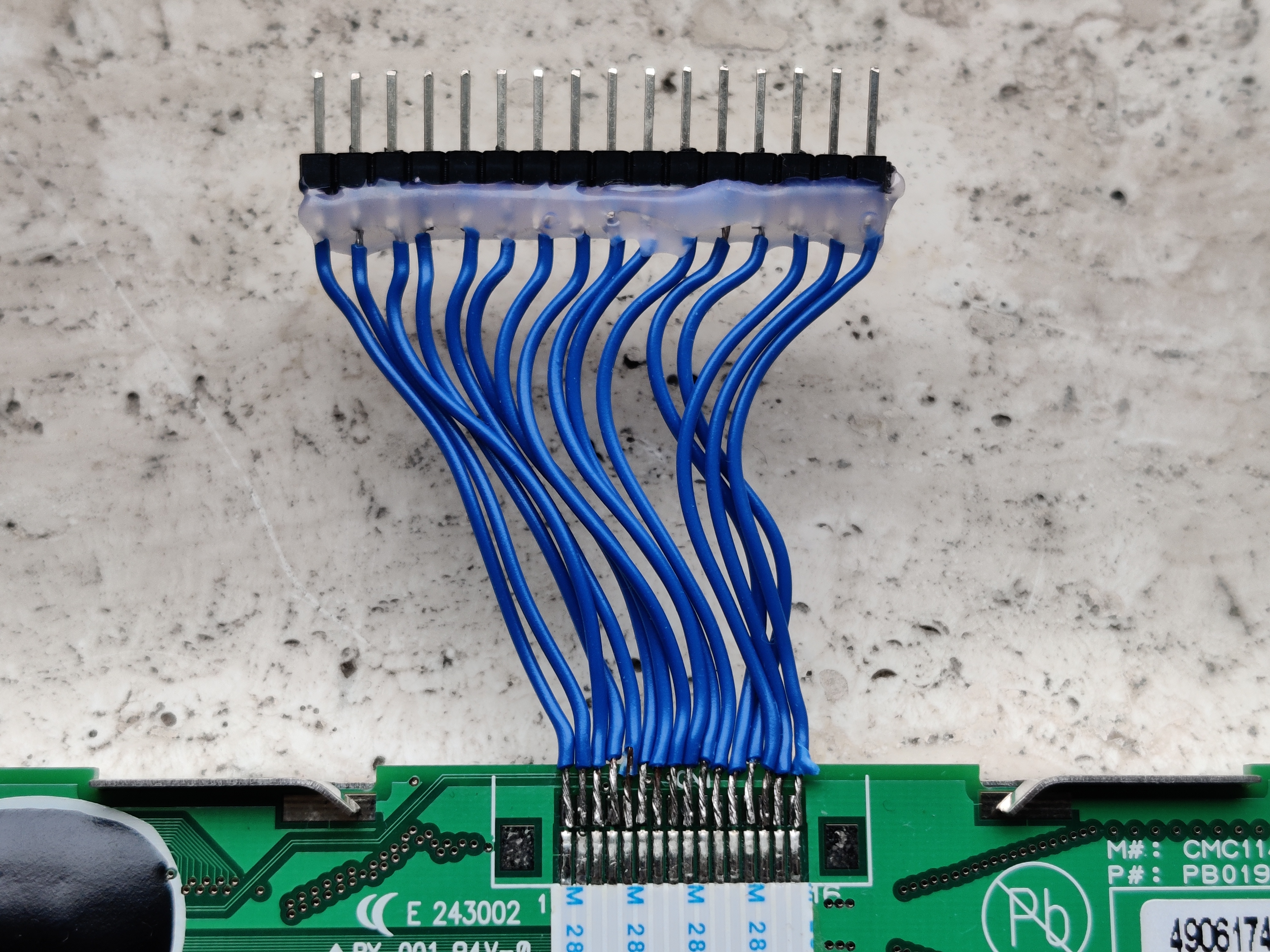
Improvised connector
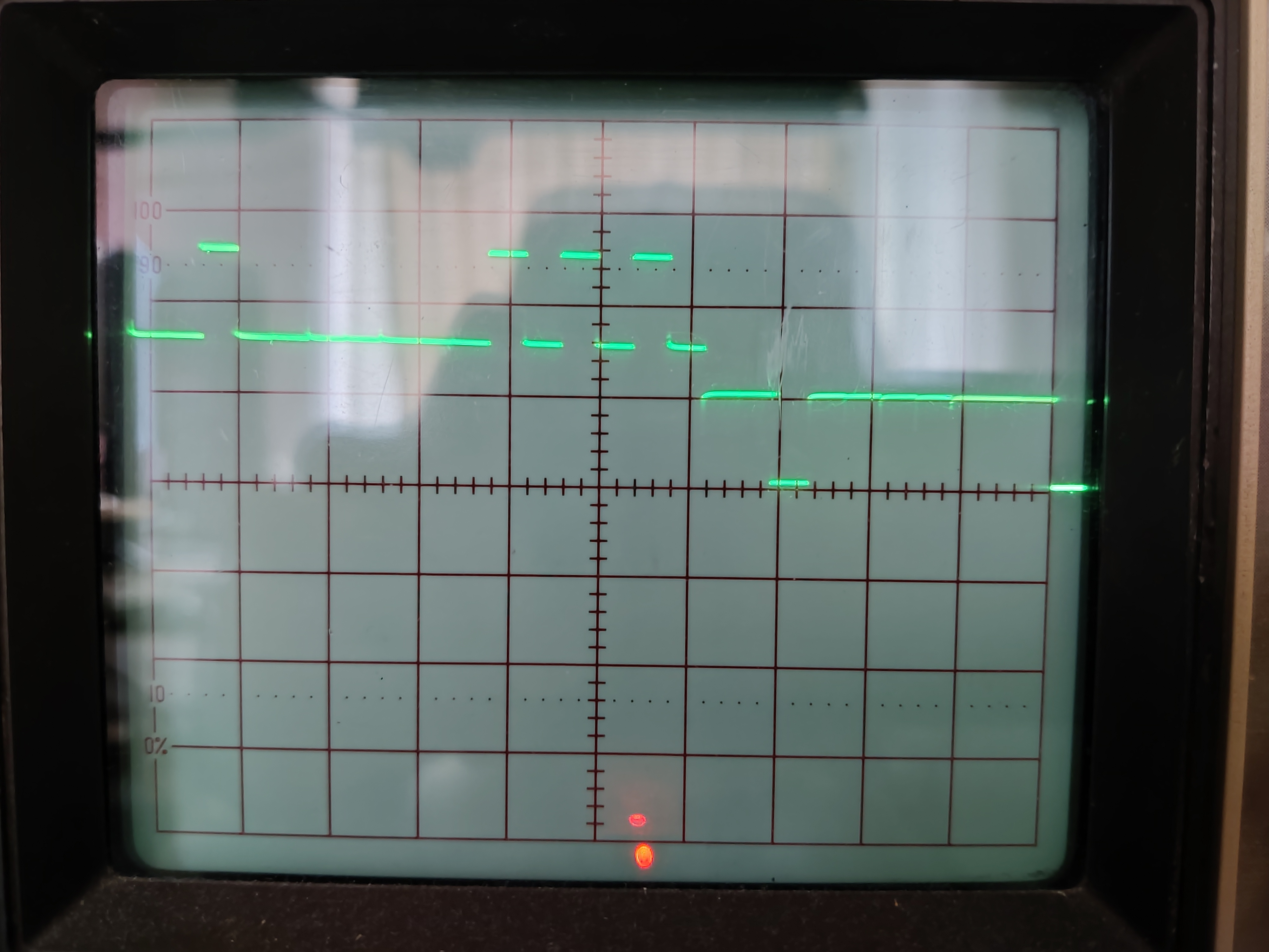
Driver IC waveform
I considered programming the Arduino in a way that test's all the possible pin combinations to drive the display but assuming that every pin combination requires about 1~2 seconds to test it would take more than a month to test all the combinations. And then I would need to set up a camera to constantly record the display to know which combination worked.
Needless to say, I abandoned this idea very quickly...
Coming back with a vengeance
I wasn't certain that my Arduino was even driving the LCD correctly to begin with. That's why I ordered a 2x16 display with an ST7066 so I had something to compare against.I was able to drive the 2x16 display but the 1x32 still didn't work.
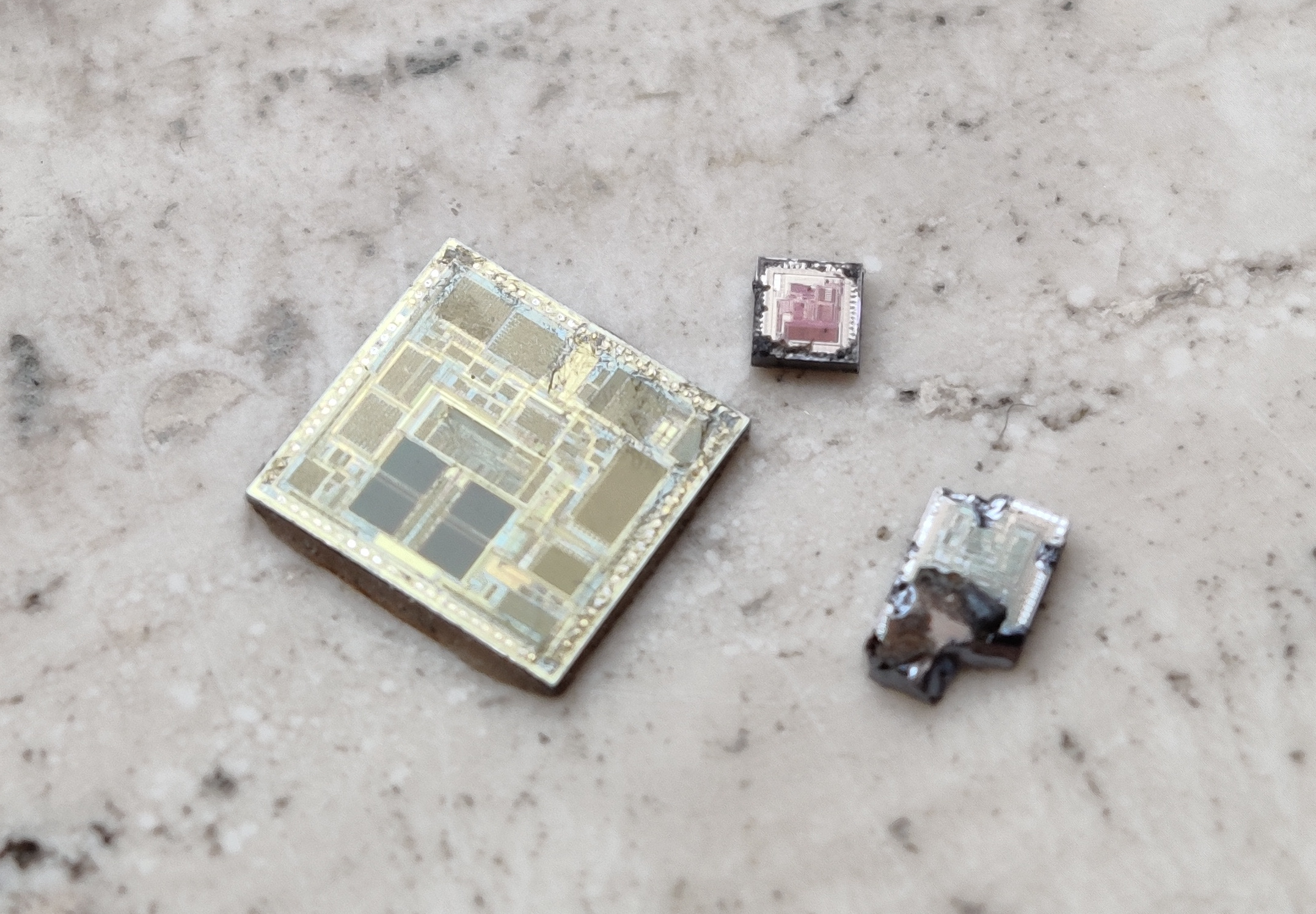
As a last resort, I could try to decap the chip to measure what bond wires go where and figure out the pinout that way. But I had never done this before. I also don't have access to nitric/sulfuric acid. However, I did find some videos of people using sandpaper or a heat gun to release the chips from their packages.
I started out with sandpaper. But while sanding I quickly realized that the chip under the epoxy couldn't be a ST7066 after all. The ST7066 can only drive 16 characters. So it is often paired with a second chip (ST7065 or ST7063) to drive additional characters. I had expected to find two chips under the epoxy but there was only one. Now that I think about it, two chips would have never fit under that single blob of epoxy. I figured that I still had a driver from the same (or compatible) family of chips as the external components are the same as the ST7066. But that still leaves a lot of possibilities.
The only way forward I saw was fully decapping the chip and seeing whether I could find any markings on it that would tell me what model it was. But for that I needed a microscope...
Getting a microscope
I found a second hand microscope for only 25 euro that looked very similar to the one I once used in high school. It came from a veterinary clinic that had closed its doors. The veterinarian told me that he had used it to examine animal faeces...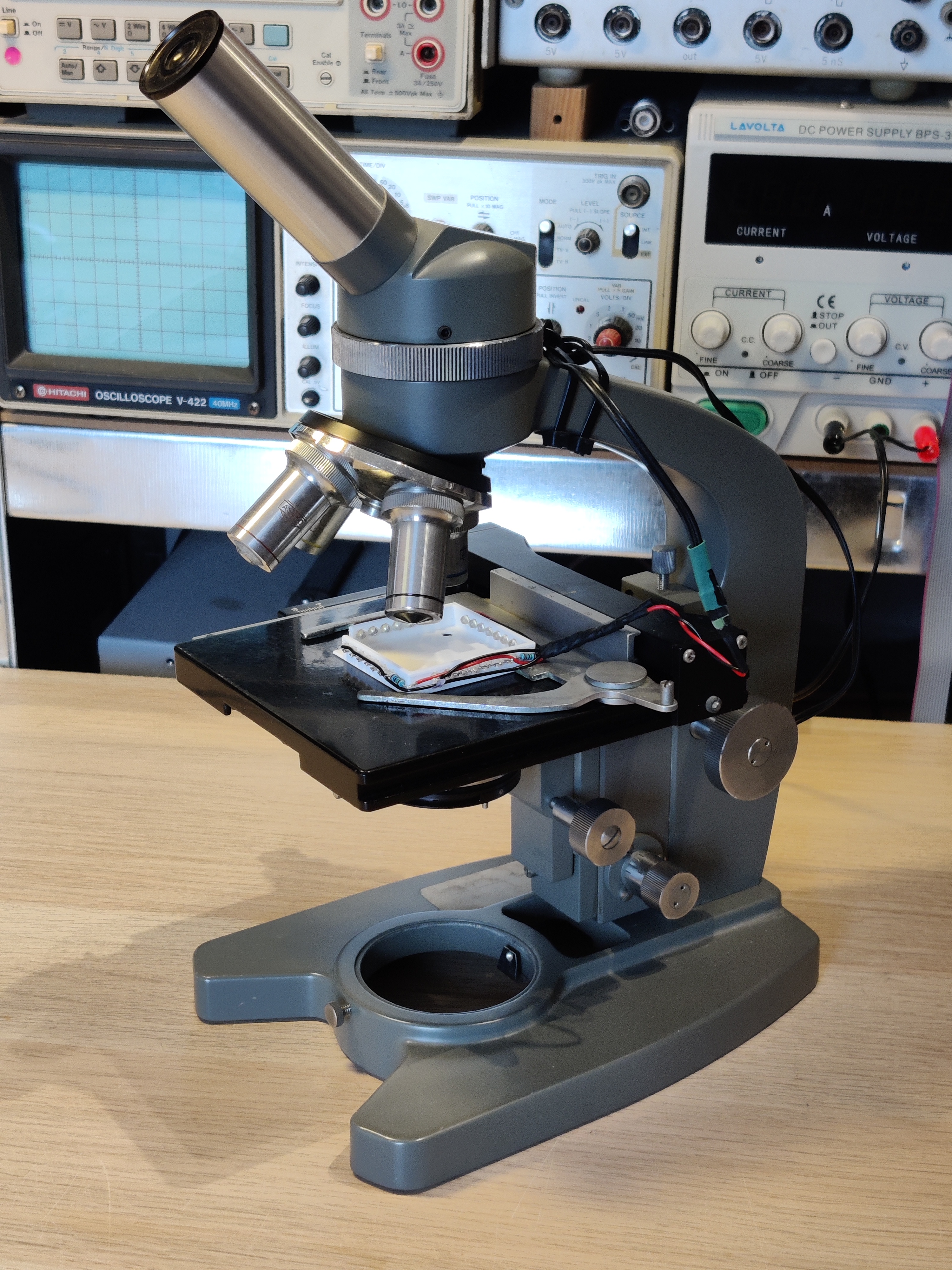
So it was time for a little side project. I quickly developed this tray that has 28 white LED's around it to flood the object with light. The LED's need to light the object at a near 0° angle because the high magnification lenses of the microscope need to be <1mm (~3/64 inch) above the object to focus.
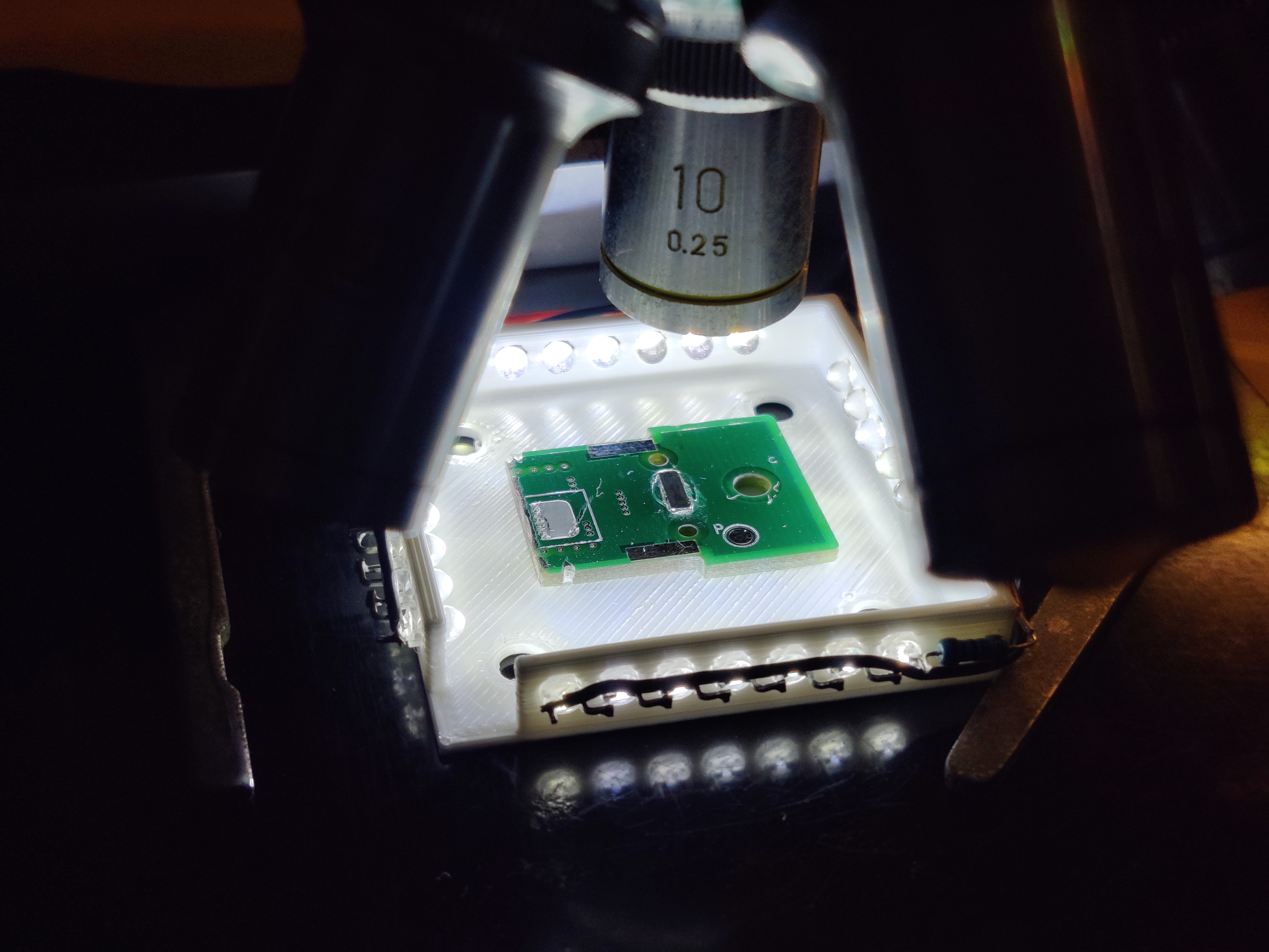
Light tray
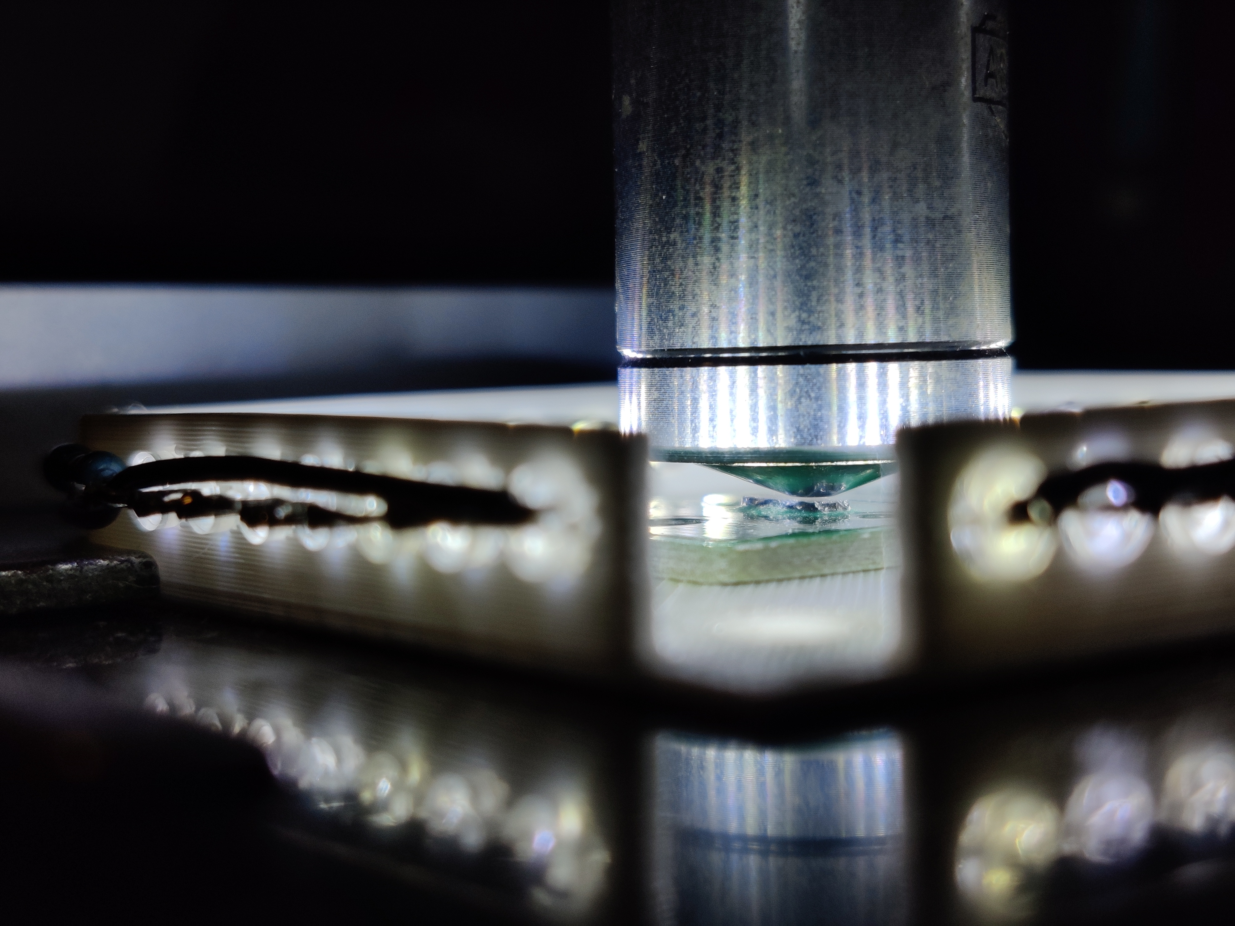
Lens clearance
Decapping chips
I decapped some more chips from scrap boards to practice. This time I used the heat gun technique. I was able to read the markings on the chips I successfully decapped and felt somewhat confident I could read the markings on the display driver.Side note: while looking for decapping techniques I came across this page that list a few interesting ones that I hadn't seen before.
Practice chips
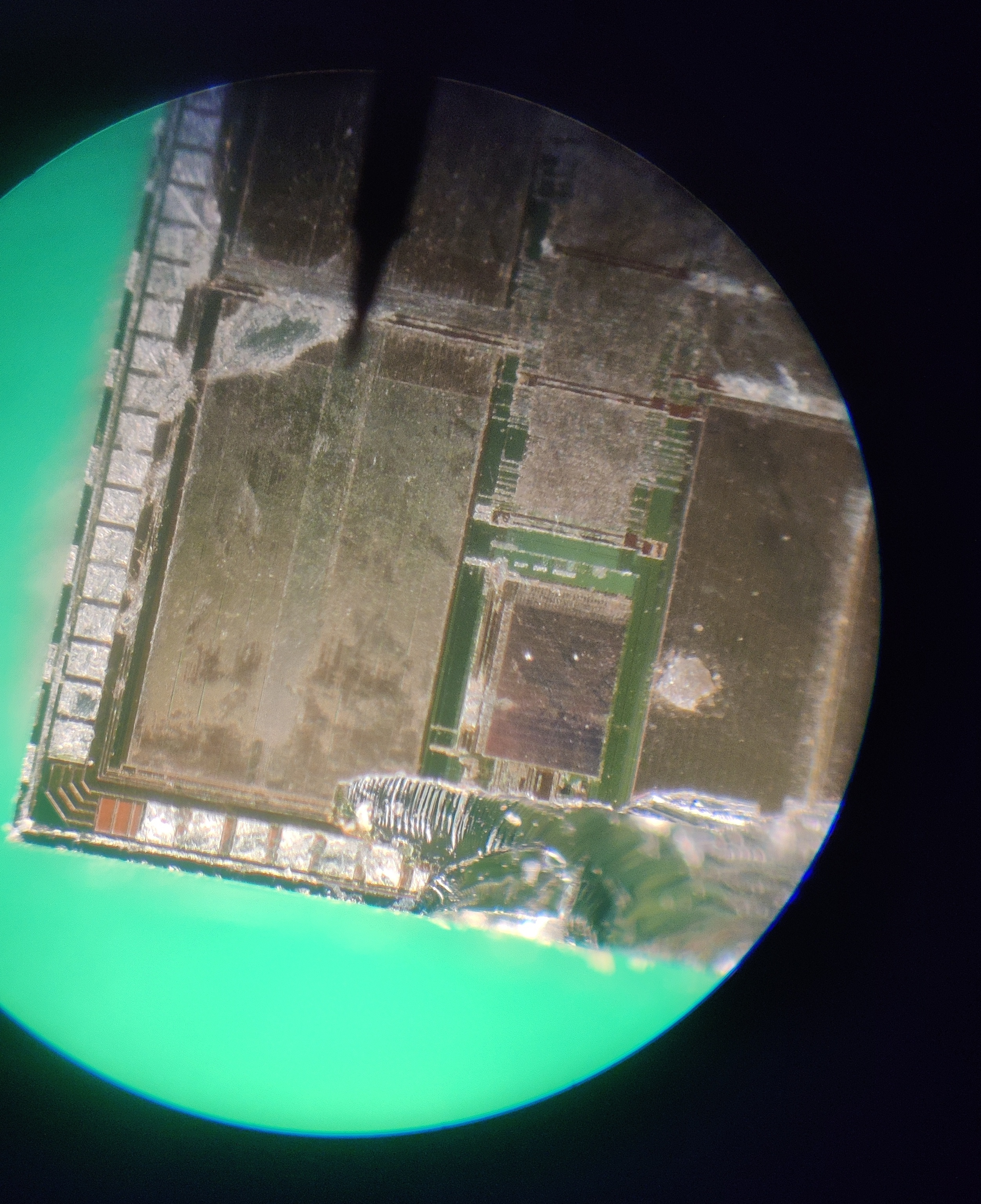
Decapping the display driver with the heat gun technique was a challenge. I did get it out of the epoxy but there was still a big piece of it covering the layer of transistors.
Ironically I reglued it to a piece of PCB to make it more handleable and removed the last bits of epoxy with a file and did the final passes by very lightly scraping away the material with a fresh exacto blade. This somehow didn't damage the surface of the chip but did remove the epoxy. I haven't seen this technique used anywhere else before. But it worked quite well.
In hindsight I probably burnt the epoxy which caused it to harden. If I had taken more time to slowly heat the epoxy to its glass transition temperature and kept it there while removing it I probably would have had an easier time removing it.
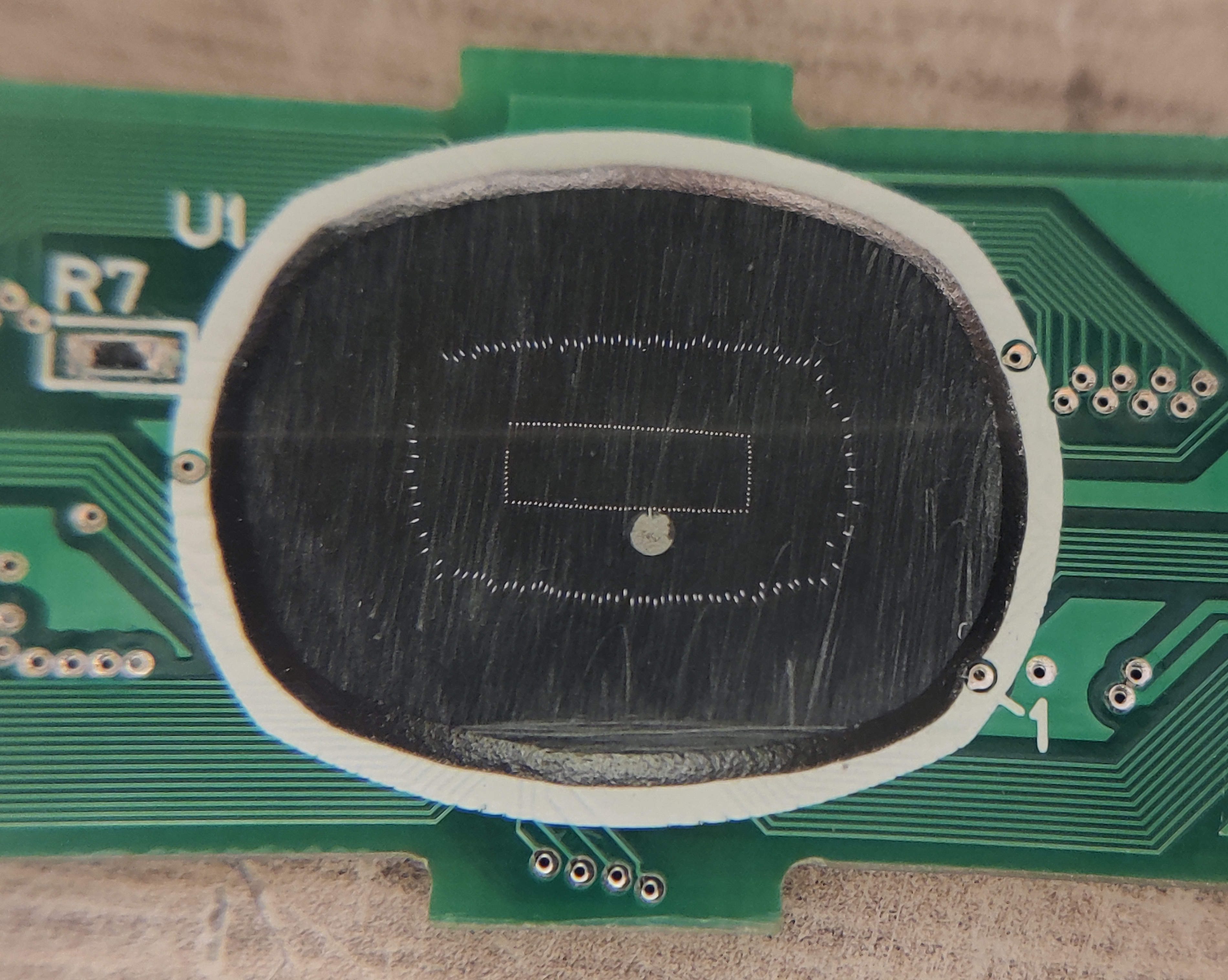
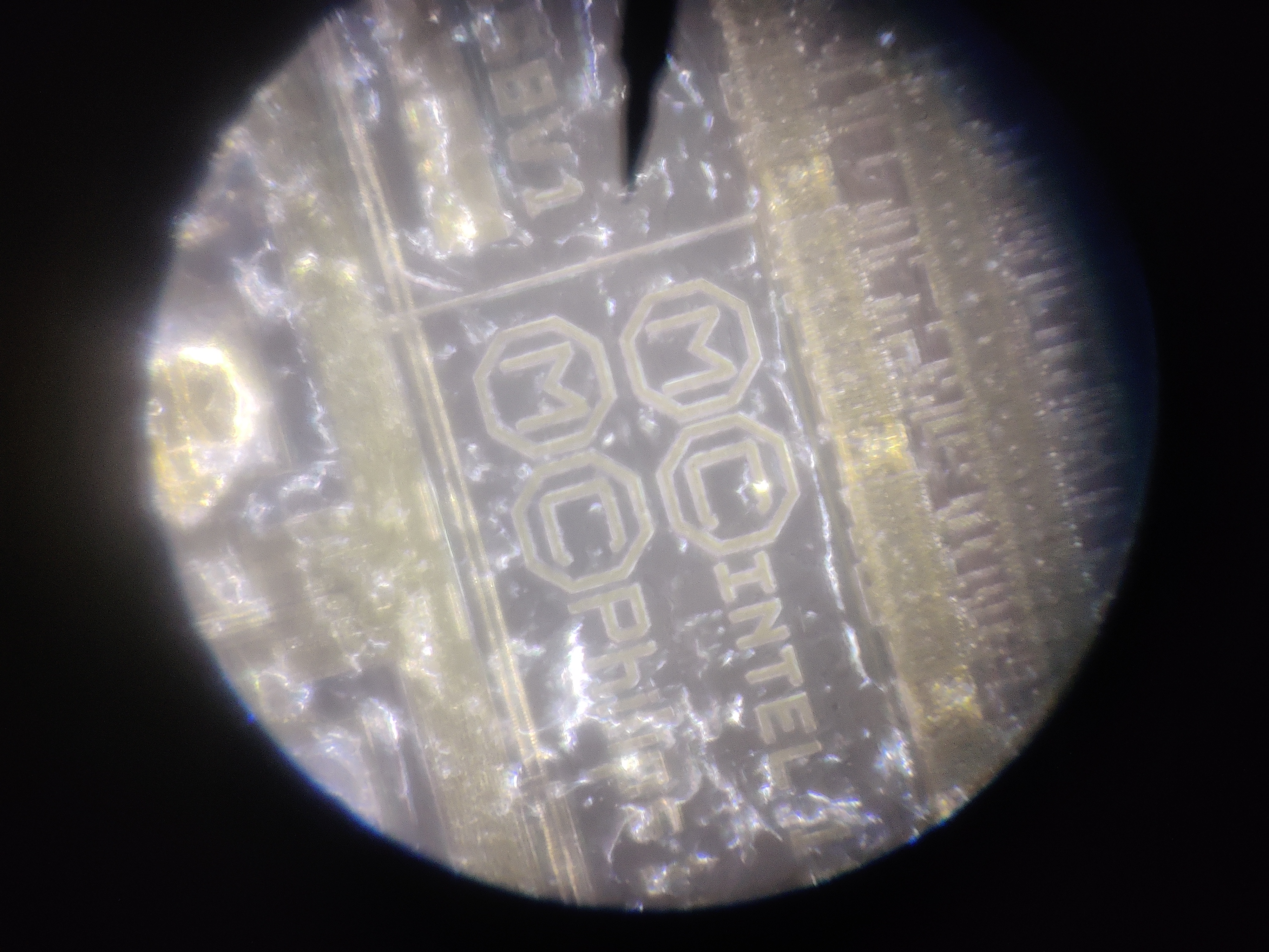
I was able to examine the chip but the markings ended up being just too small to read with my second to last magnification (200x). I wasn't able to see anything with the final magnification (500x) because the lens blocked too much of the light so see anything.
Driver IC glued back onto piece of PCB
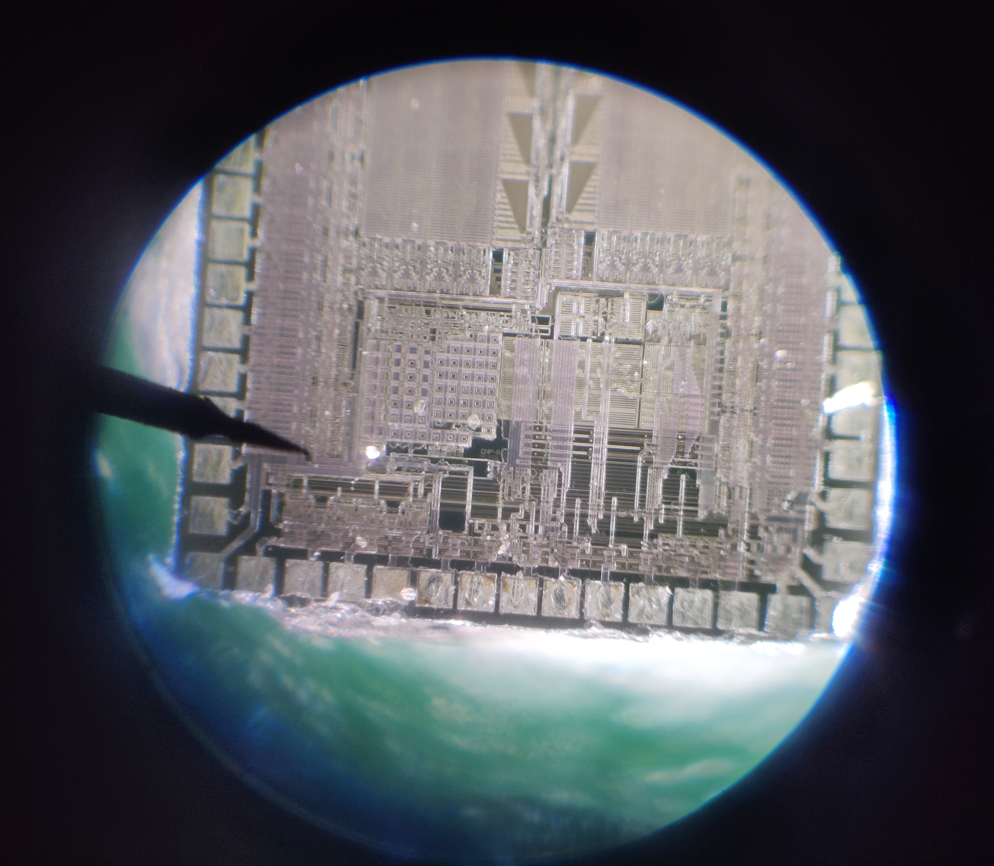
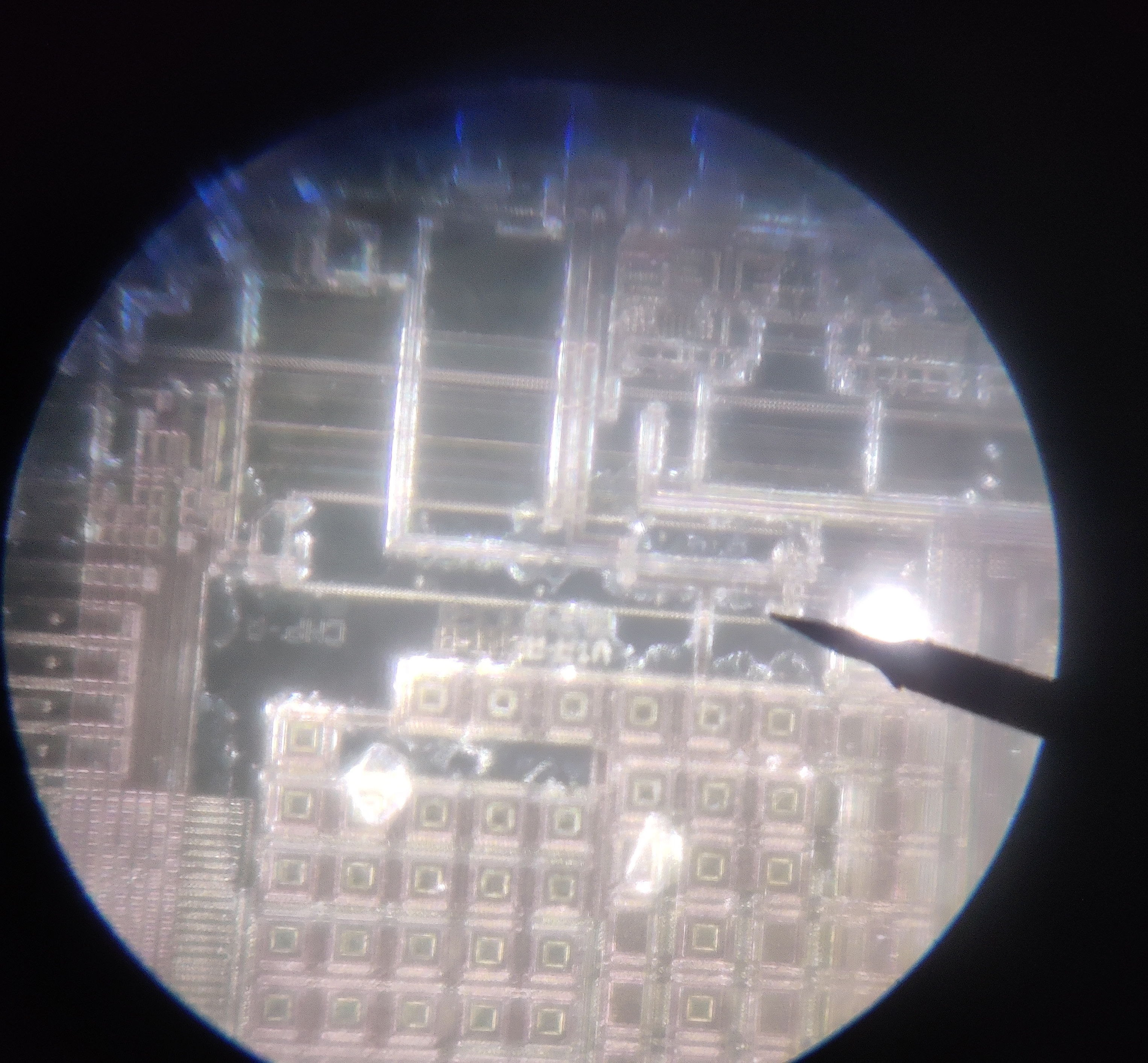
Illegible text
Another approach
I knew there were still some clues to be found. The external components on the board form a voltage divider. The different voltages connect to the IC. I measured where the different voltages connected to the chip and in what order. I could then match this to similar chips in the family.I found a list of datasheets for a lot of LCD drivers chips. When looking through a bunch of them I realized that the chip I had was very rectangular compared to all the other chips in the family, except for one!
The ST7070 has (as far as I could measure) the same dimensions as the chip I had decapped. I compared the measured connections of the voltage divider to the locations in the pinout of the chip in the datasheet and it looked very promising. By matching these connections I could further deduce where all the other wires went. I was able to trace the data bit and instruction pins to the pinout of the flat cable!
To keep track of what all of the wires connect to I made a quick and dirty diagram in Gimp.
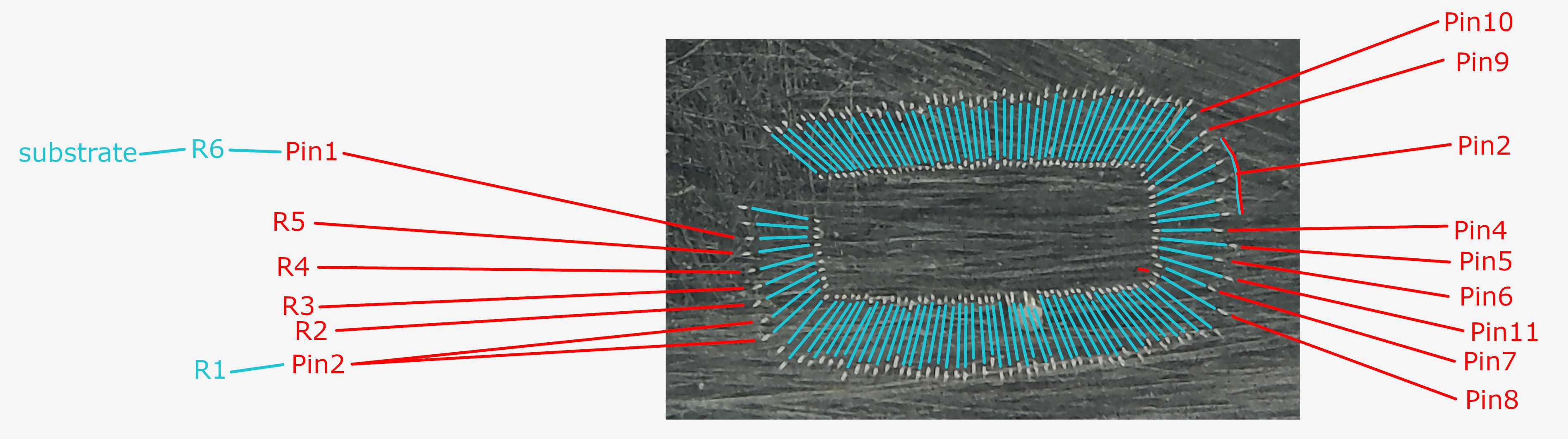
Quick and dirty connection diagram
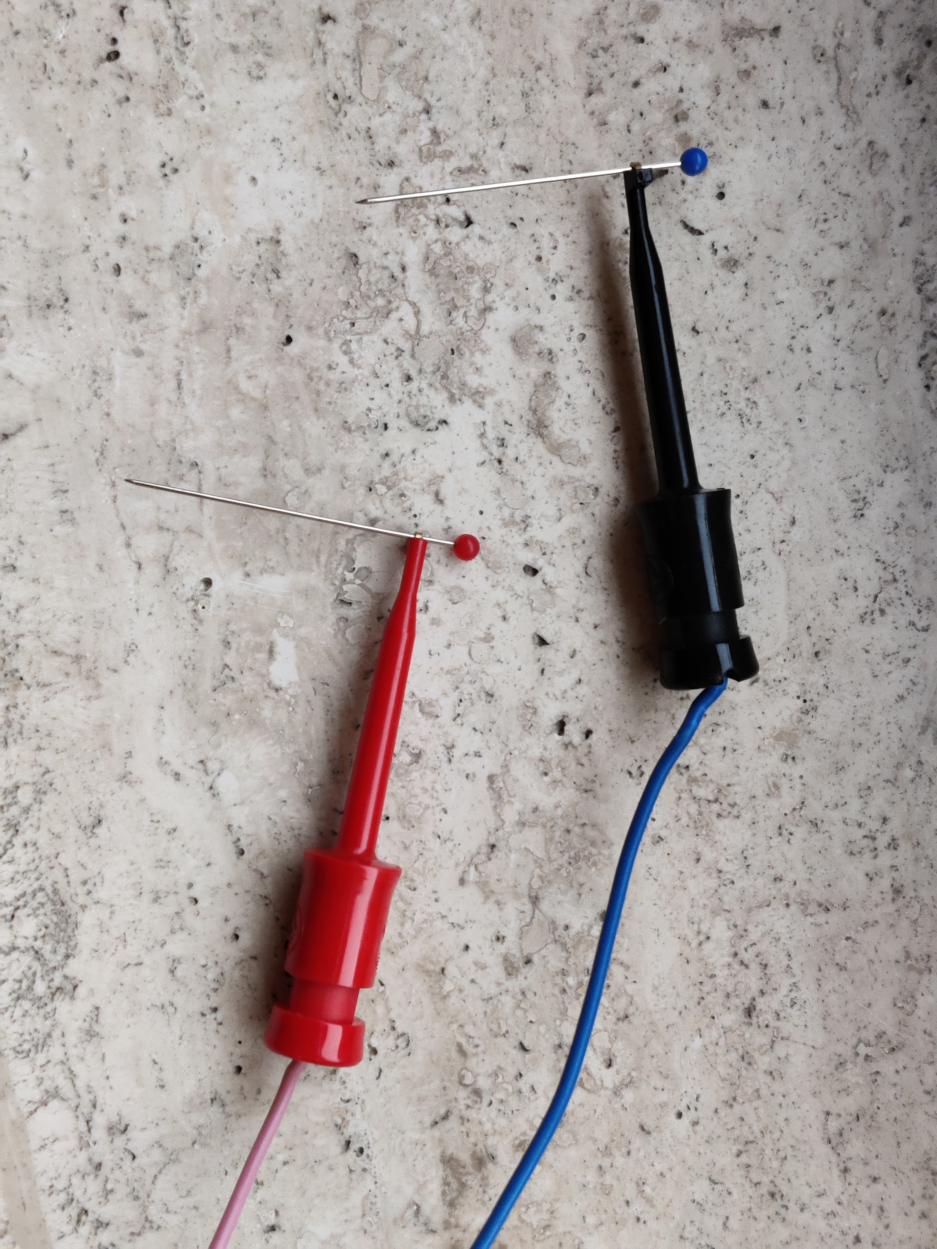
Dressmaker pins used as probes
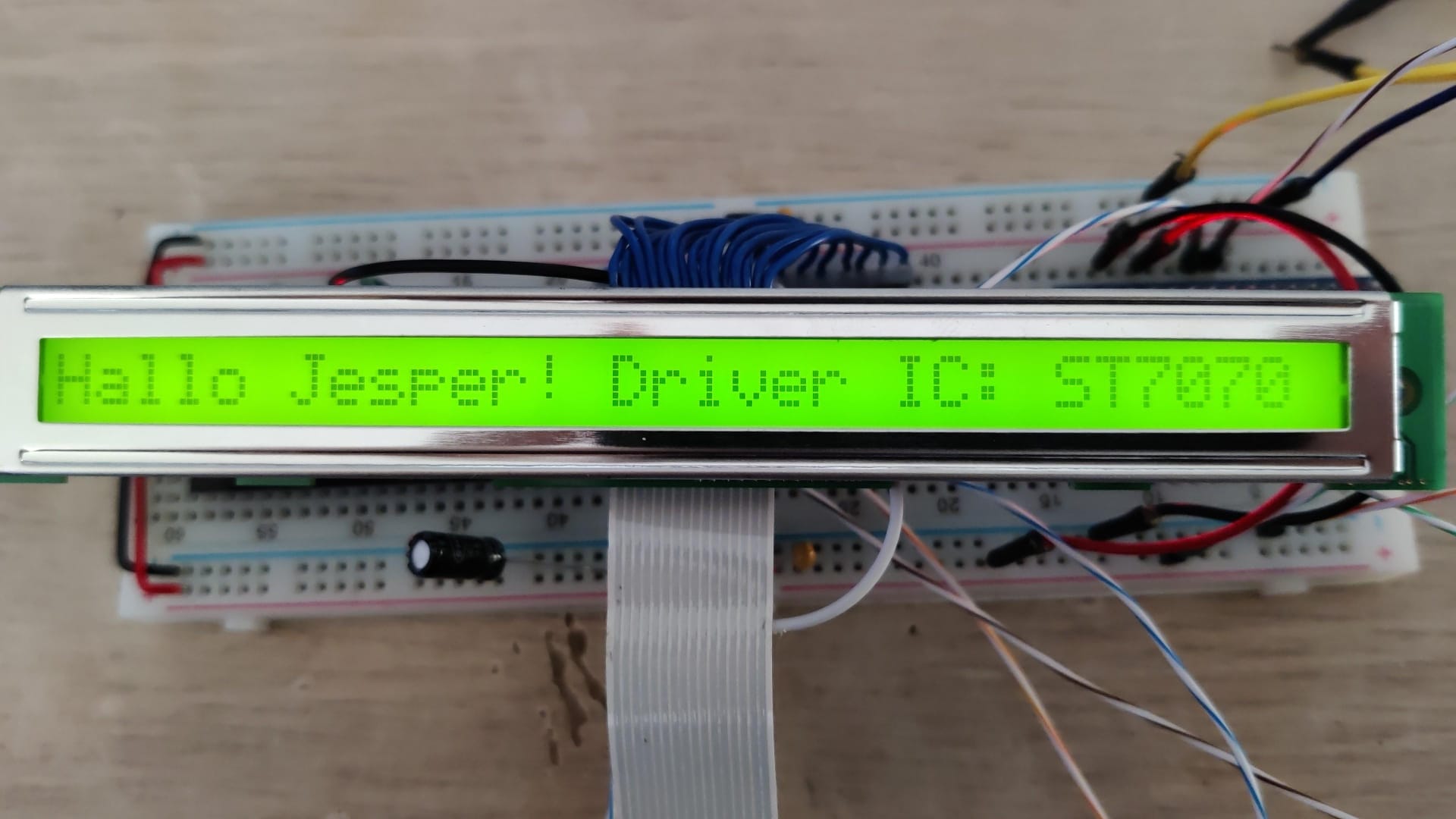
The display finally working
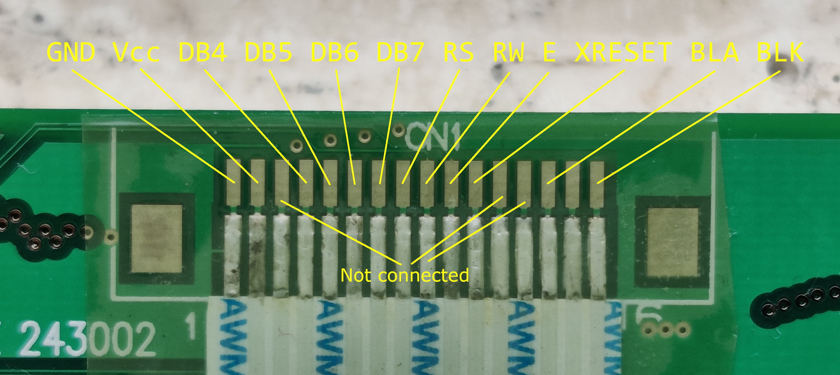
Pinout
The way the driver is connected to the PCB is somewhat strange though. D0-D3 are connected to Vcc as well as the Parallel/serial connection pin.
So the driver is essentially locked into 4-bit serial mode. Leaving out 8-bit serial and SPI. Another 3 pins are not even used which seems like wasted opportunity, but I shouldn't complain.
Adapter PCB
Because the displays come with an FFC cable already attached I designed an adapter PCB so I can easily connect to it using pin headers instead of having to solder wires to it like a caveman. I designed the PCB using KiCad, panelized it using KiKit and ordered them from JCLPCB. I simply got the connectors from AliExpress. That link will probably already be broken by the time you are reading this. But these connectors are very common so I am not worried about finding another source for them.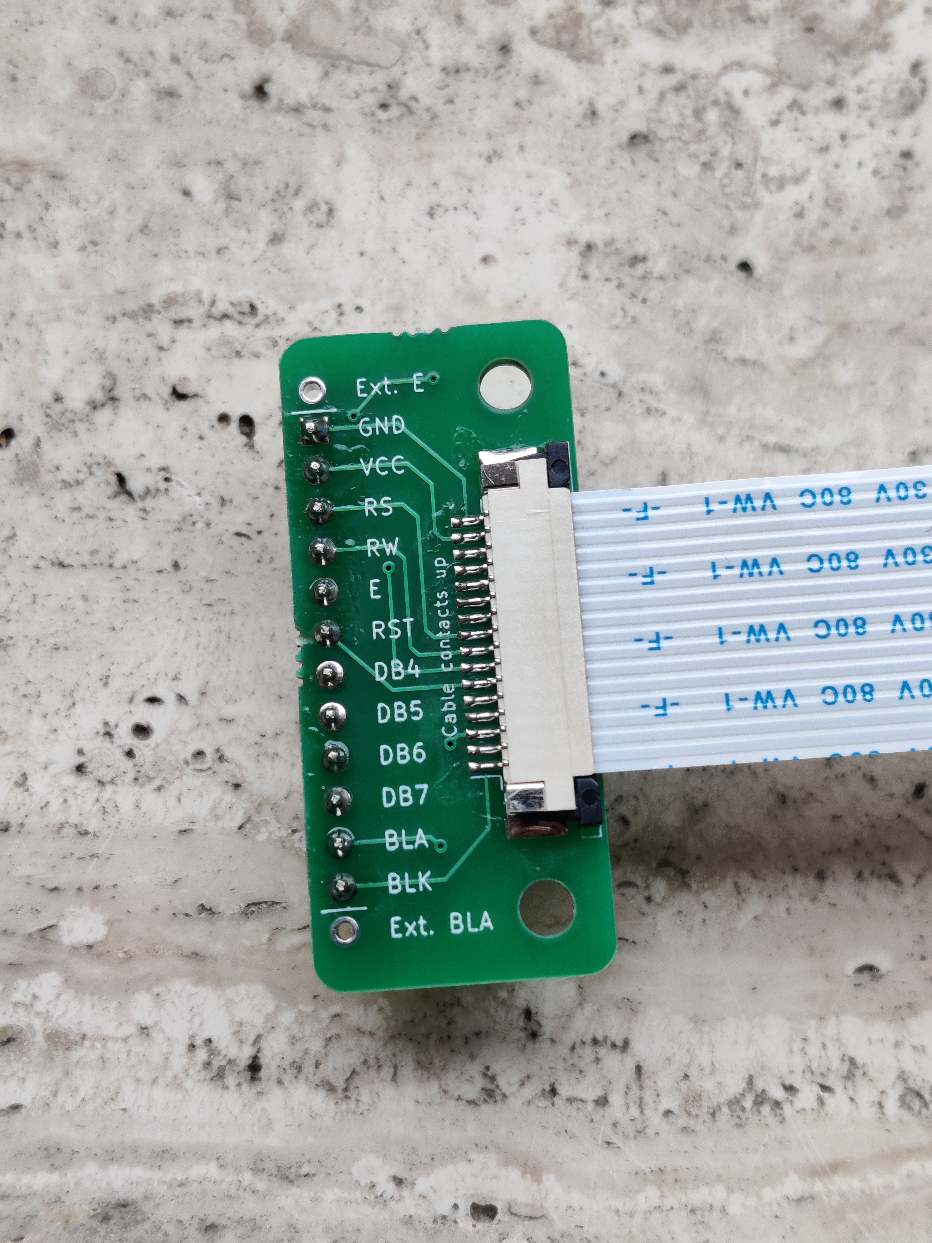
Adapter top
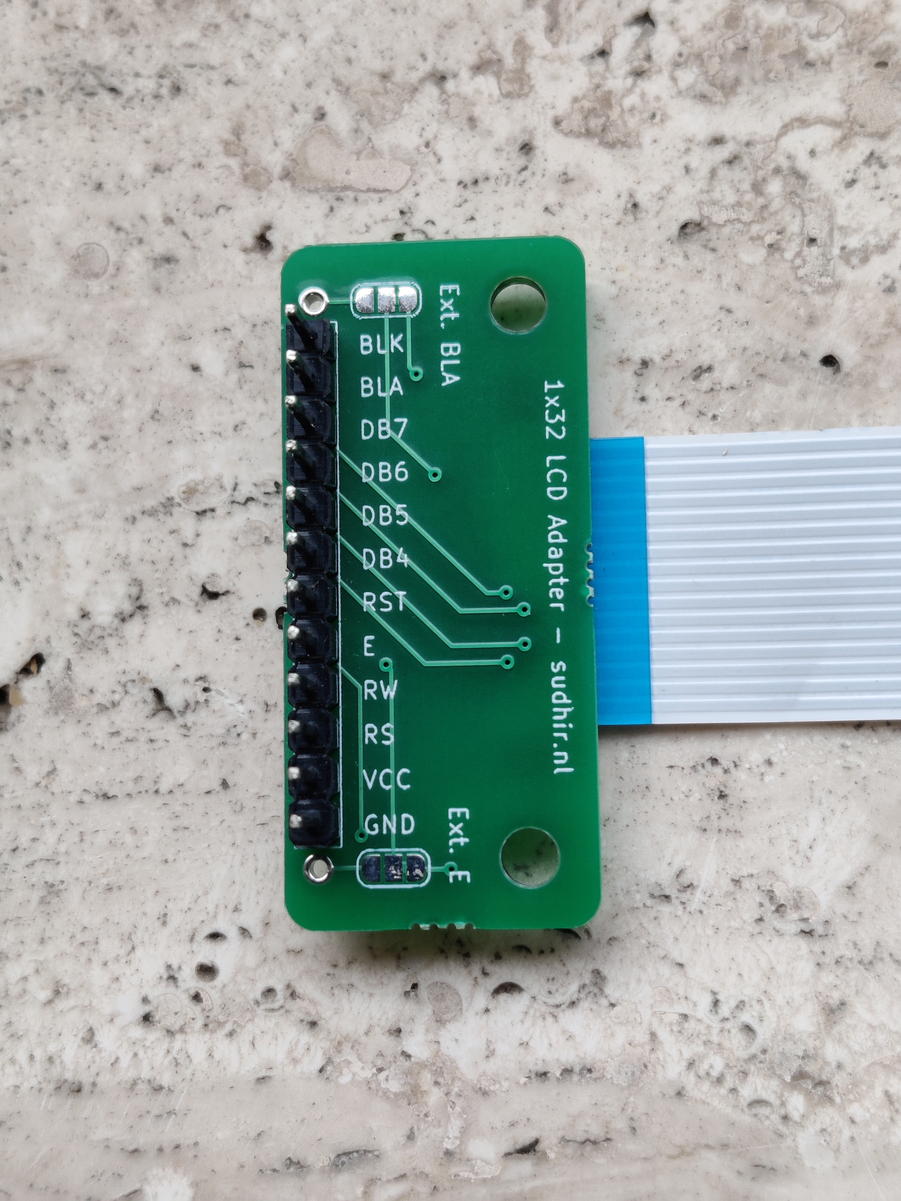
Adapter bottom
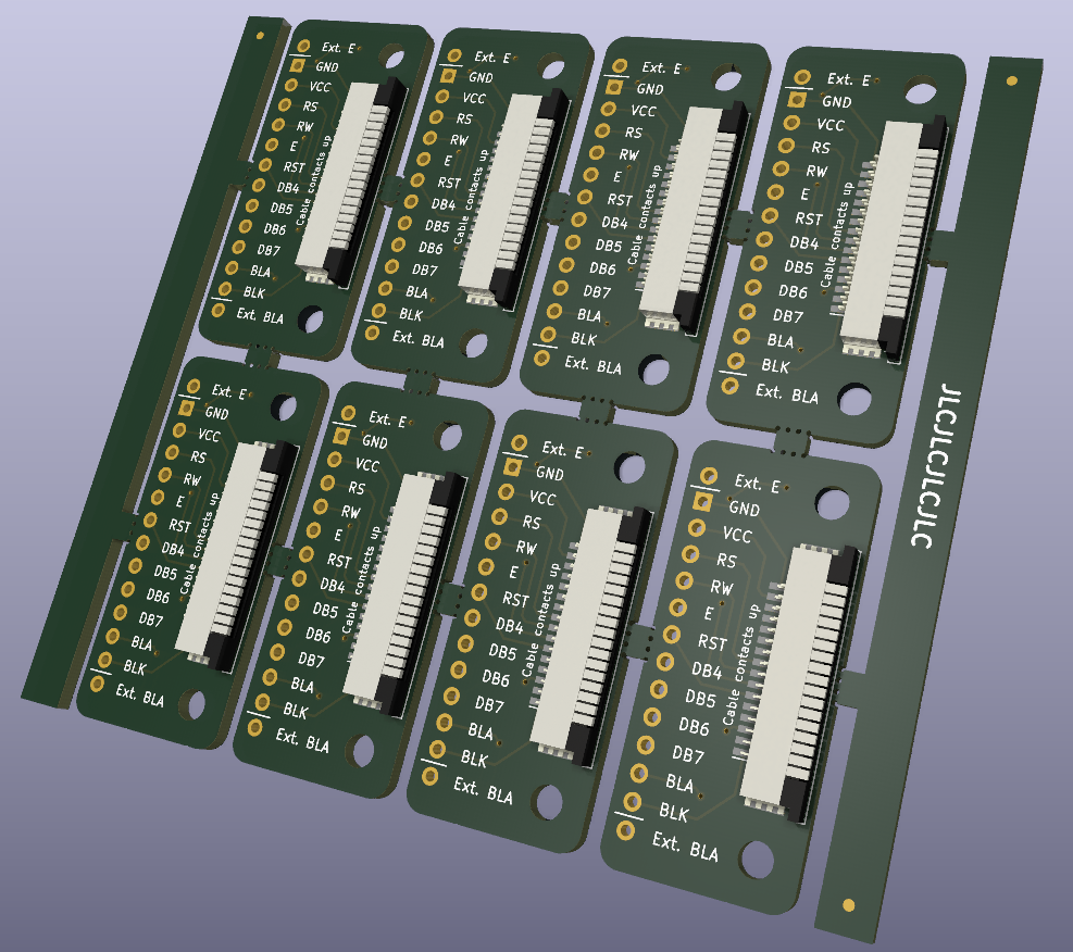
KiCad render
Custom library
Next I plan to write a custom library for the display as I can only write to the second half of the display as if it were on another line using the standard Arduino library. The ST7070 is also special in that it has a different character set to the ST7066. So this should also be included in the library.When I finish the library I will post it here.